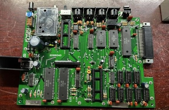
A little while back, I picked up a Radio Shack TRS-80 Color Computer 2.
It was on offer from an estate sale not too far away, and from what I saw it was missing a keyboard. I threw $50 at it thinking ‘how bad could it be’.. and long story short, it had seen better days.
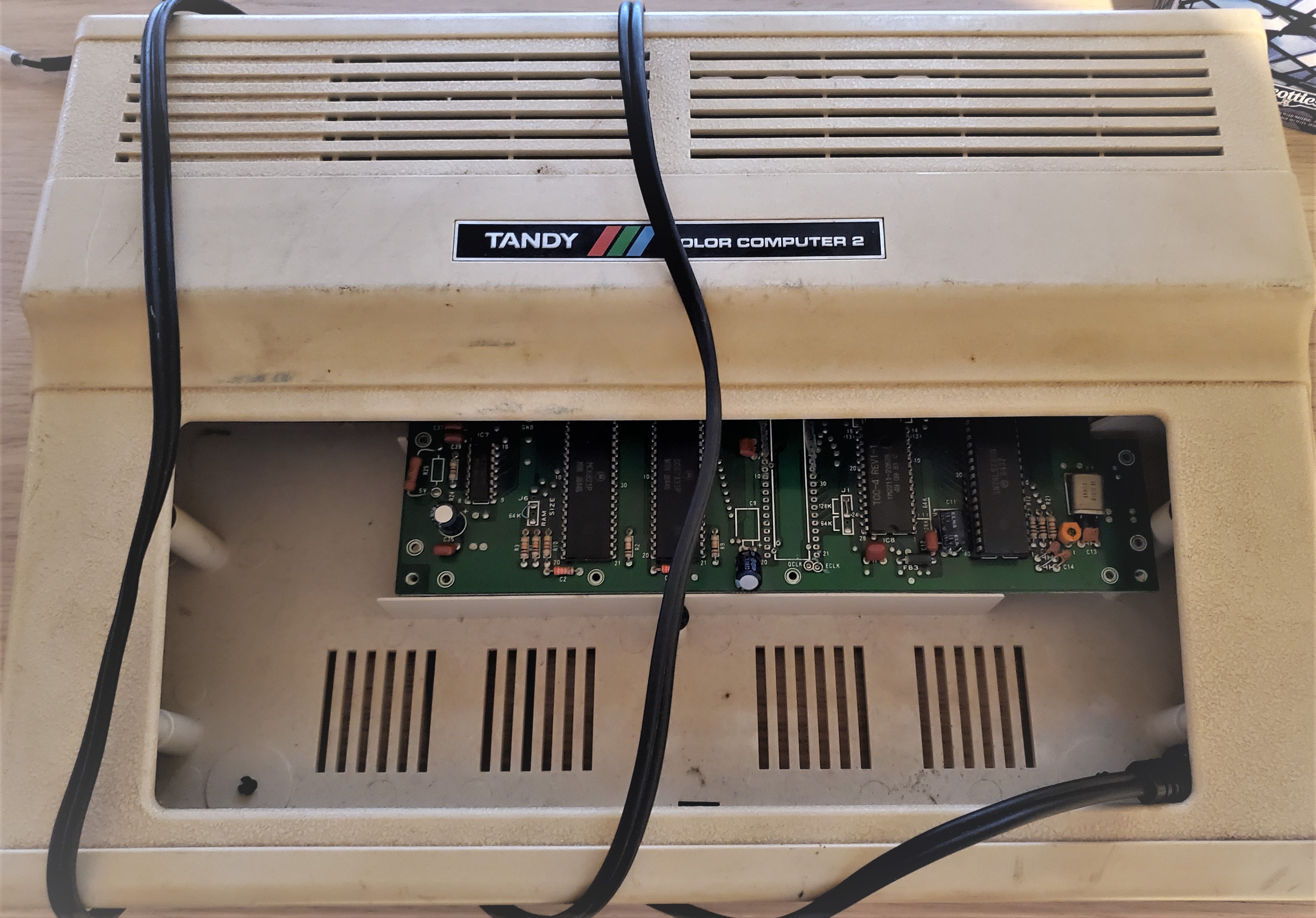
It got to me missing the ram and missing the CPU of which 30 pins were competently desoldered before whoever was working on it decided to cut rest out with a Dremel or something. I just don’t understand.
Normally I would have considered it a lost cause, but it happened to have one of the semi-rare XC80652P or MC6847T1 VDG chips in it that include lowercase characters. I spent some time reconnecting the cut traces as best as I could and managed to get the machine sort of working. Basic seems to work fine but cartridges or my CocoSDC do not seem to work so all isn’t right. There does not seem to be a schematic available for this version of the board so it’s entirely possible I have guessed incorrectly on a connection or two. There could also be something bad on the board somewhere that may have been the reason it was left for dead in the first place. (I hear there is a reproduction board in the works so if that materializes, I have a path forward.)
I wondered how different the chip was from the original, and if it was possible to install it in my other Coco2. I found the datasheets for both versions of the VDG, and the pinouts were different enough that it was clear to me that it would not be a direct swap. I put it aside for a while, but it wasn’t long before I turned up a couple of articles in ‘the Rainbow’ detailing how to install the chip in a Coco 1! I then set about following the details in the articles to see if this indeed would allow me to use the T1 VDG in my normal Coco2. (Articles care of the Color Computer Archive, linked at the end of this post.)
Let’s Do This
The initial article details how to wire the new VDG in and set some switches up to pick something to do with the colours in a certain video mode. I kind of glossed over that but a further article explained how to have the switches be a default and a TTL chip could be used to control the state of the switches via software. This sounded great so I attempted to include those changes and would circle back to this aspect of the install later. (I haven’t yet, so this remains untested on my board.)
The articles are well written, but they could have done with more in the way of illustrations. I attempted to create a schematic directly in KiCad from what the text explains you are to do. This is what I came up with.
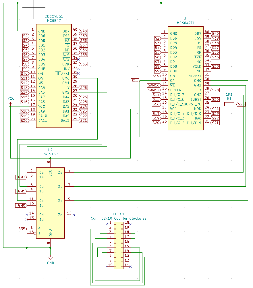
In the first article, Tony explains that the 74LS273 logic had been moved in to the new VDG, and provides a point to point list of connections to make in place of the removed 74LS273 chip that are required for a Coco1 with a revision F board. He further explains that other boards may require different wiring and that it was up to the reader to experiment and determine the correct wiring. He also mentioned something about a contest where if people sent in the wiring schemes for a given board, he would publish them in future articles. I searched in vein, but never found anything in the way of wiring diagrams for other boards. Maybe it wasn’t a contest. No matter.
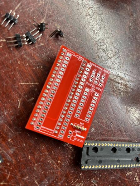
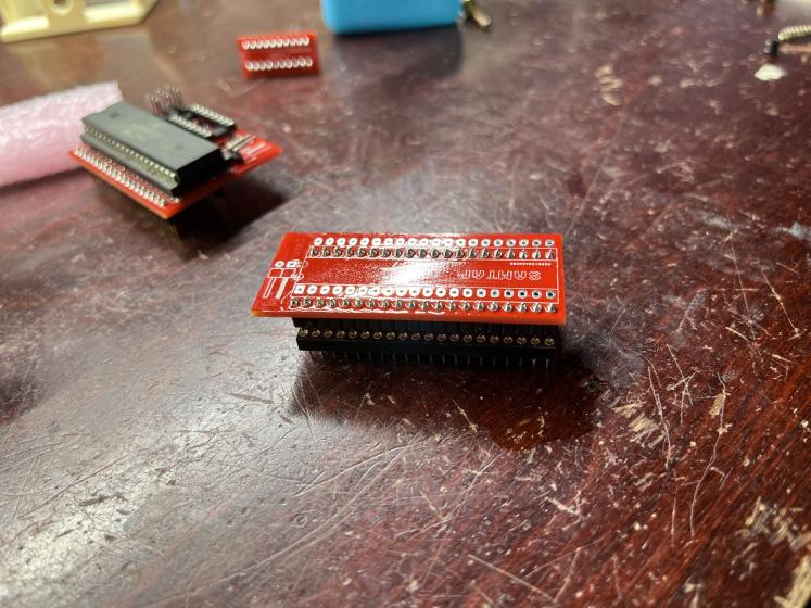
I set about making three circuit boards for the project. I didn’t like the idea of leaving wires floating around in the unit, so I envisioned one board to act as the ‘wiring plug’. I also wasn’t keen on soldering wires or clipping wires onto my SAM chip, so I thought I would make a ‘tap board’ that would sit under the SAM chip. And finally, the main board that lets you plug the new VDG in and configure the mysterious video mode switches.
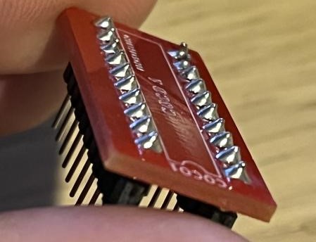
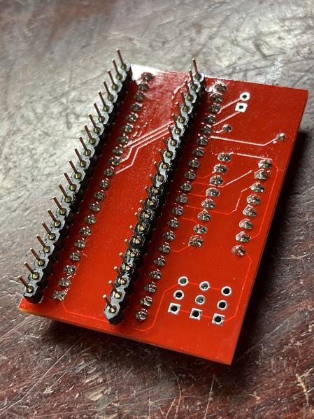
Here are the boards!
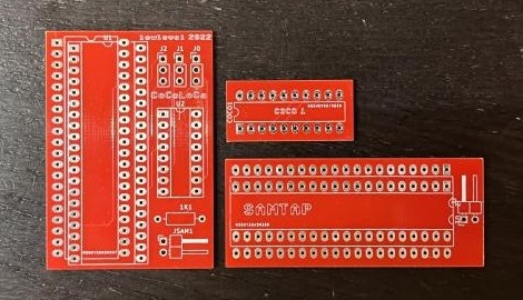
I would like to state, that this project was sponsored by PCBWay. In the spirit of encouraging open source and development, they were kind enough to cover the production and shipping of the printed circuit boards you see here. As always, I am quite happy with their service and I’ve had nothing but good interactions with everyone there thus far. That being said, I have and will continue to look to PCBWay for all my PCB needs, sponsored or not. Again, thank you PCBWay!
Building The Boards
I soldered in all of the parts I had planned to use and while I knew the Coco1 plug board was likely to not work for me with my Coco2, I figured it would be a good starting point.
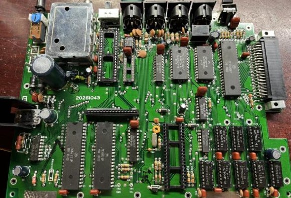
Prepare the Coco2
Now I had to get the Coco2 ready for the boards. The easy part was removing the SAM and VDG chips… but there is of course that little 74LS273 that has to be removed.
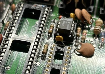
Desolder the 74LS273 and install a socket.
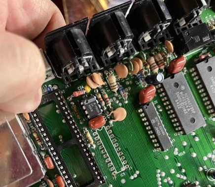
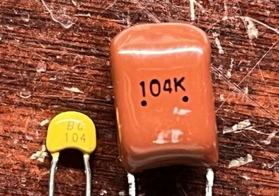
There is a rather large 100nf capacitor here that will prevent us from installing configuration plug if we don’t do something about it. Maybe I’m weird, but I found it rather amusing how large it was vs a modern 100nf cap that you would typically see. Here they are for your enjoyment.
Here is the smaller cap installed. The 555 timer had been replaced earlier to get rid of a big yellow bar on the left of the screen. Normally that would be soldered in.
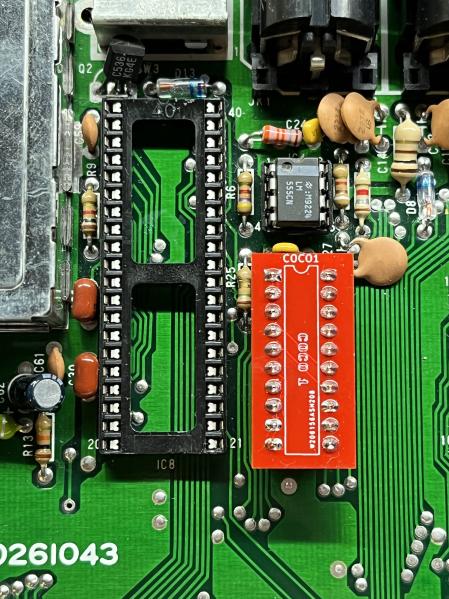
Now we can install the configuration board. This ends up being kind of tall and will require us to use some extensions on the pins for our main board. On the final configuration plug, I will try to remove the plastic ‘holders’ from the pins and shorten them, so it sits lower.
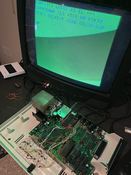
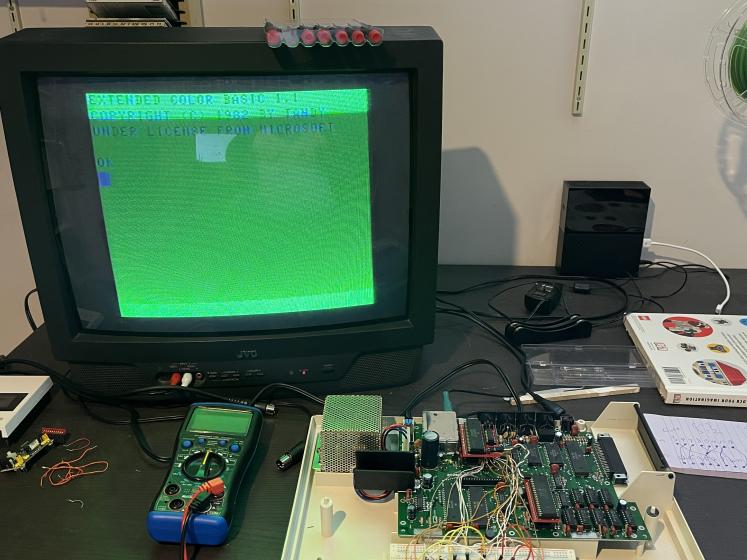
I admittedly got a little ahead of myself at this point and didn’t end up taking a lot of pictures. Here is a picture showing what I believe to be on the screen with the first power up with everything plugged in. Don’t at me bro.
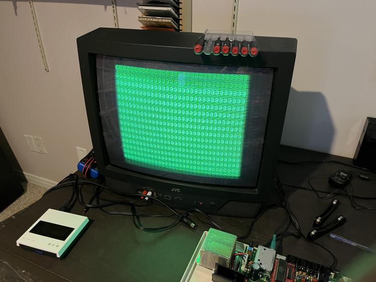
I flipped my SAMTap wires around and got something that seemed a little better and a little worse at the same time. I was rather unsure at this point, but I figured I was just seeing the coco 1 wiring not being right on my coco 2 as expected.
Trial and Error
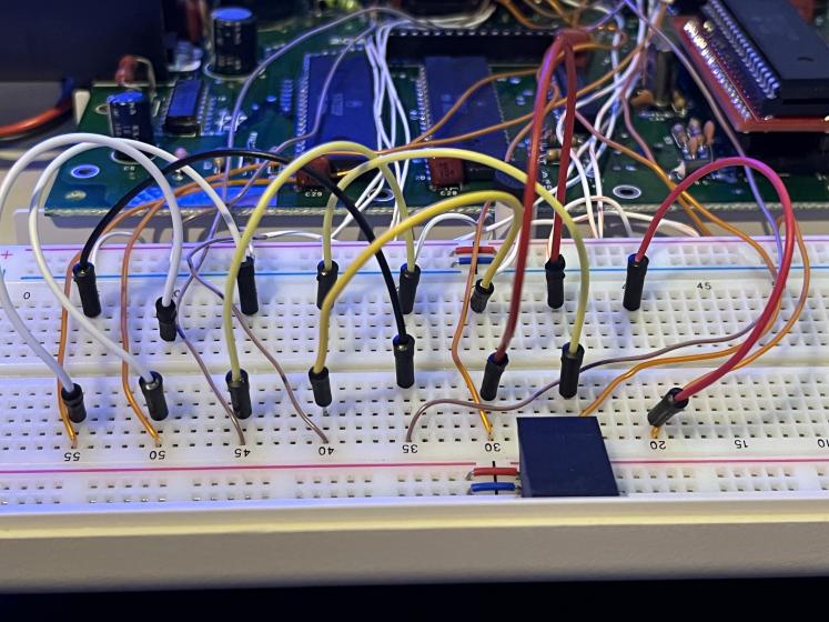
So, this is the part where it is up to the end user (me) to figure out the correct wiring for my motherboard. I decided that I should extend all the required pins to a breadboard and have some easy to move jumper wires that I could set and test.
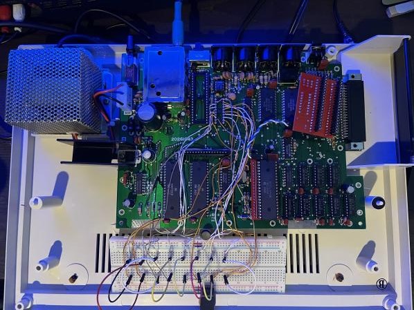
Here you can see the unholy mess of wires running from my breadboard up to the socket where the config board is to eventually go.
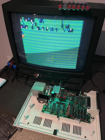
After much messing around, I eventually got to something that kind of looked like what I was expecting!
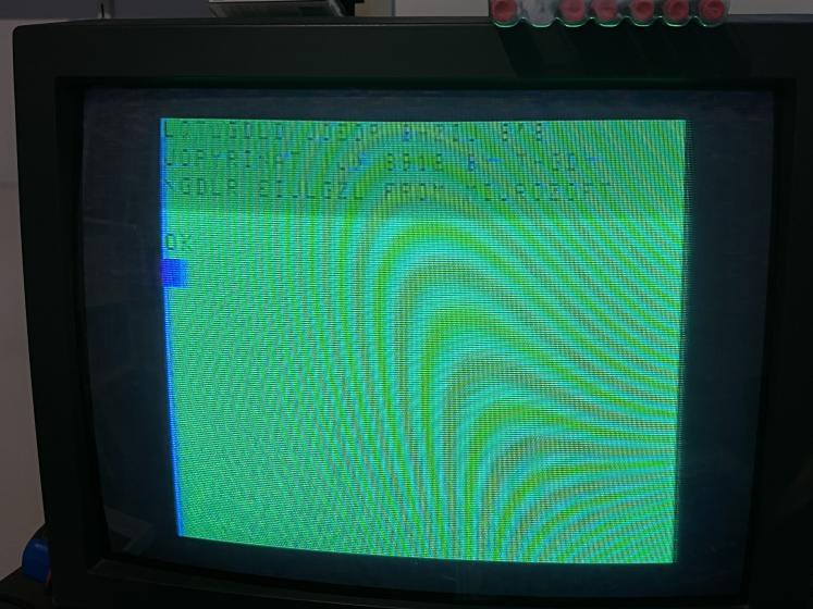
A few more attempts, and I started to see text that I could almost read! MIJROZOFT is pretty close to MICROSOFT, which means I’m probably only a bit away! It does say ‘OK’ at least, so that’s reassuring.
The VDG chip actualy has the character generator built in, so rather than mess with the wires anymore, I decided to have a look at the datasheets again and see if there was a character map. There was, and it was easy to confirm what I had suspected.
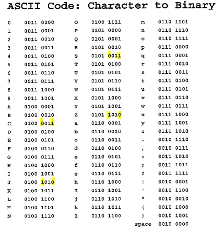
Looking at the screen, we can see that where we expect to see the words ‘COPYRIGHT’ and ‘MICROSOFT’ , that the letter C is being change to a J, and the letter S has been changed to a Z. If we look at the ASCII code or value for each of these letters in binary, we should be able to see which bit is wrong.
Here you can see that it looks like I just have the lowest bit (A1) and the fourth bit (A4) swapped.
I was one jumper wire swap away from having a working T1 VDG in a standard Coco 2!
I mapped out the wiring as I had it in a diagram so I could design a new configuration plug pcb in KiCad. Here is the wiring diagram for both the Coco1 plug (which I trust is ok but have not verified), and my working seXXXy Coco2 diagram.
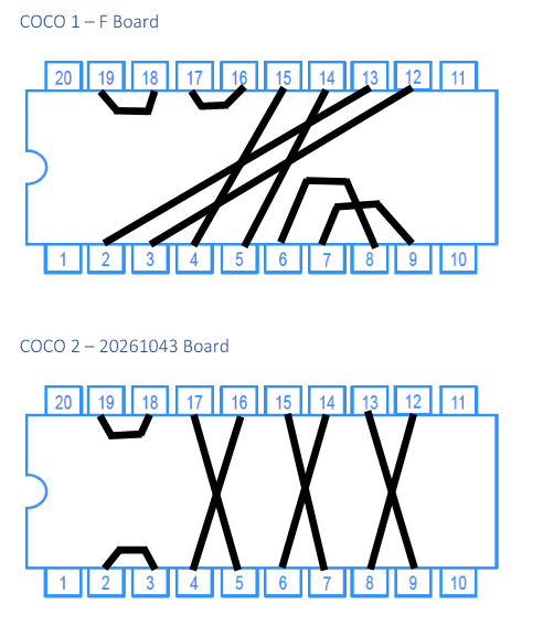
I have not yet made the Coco2 configuration plug PCB, however I will post it here when I’ve completed it. I don’t imagine many of you will be doing this, however everything is here for you should you want to follow me down this path and you happen to have an unused T1 VDG. The SAMTAP board physically interferes with the keyboard due to its height after installation, so I would suggest you don’t bother with it. Instead wire the 2 wires directly to the correct pins on the chip itself or tap in from under the board. Have fun! :)
Related Links
- Color Computer Archive / Turn of The Screw (Full Collection) Related Articles, Pages 95-103 in this pdf.
- GitHub.com / l0lvl CoCoLoCa - MC6847T1 VDG Conversion for CoCo 1 and 2
- PCBWay.com / lowlevel CoCoLoCa PCB’s shared on PCBWAY! (Soon)
Provided Here
- CoCoLoCa Gerbers Gerbers if you want to save a copy.
Todays soundtrack: