A friend of mine was having some trouble with his freshly built Replica 1 Plus.
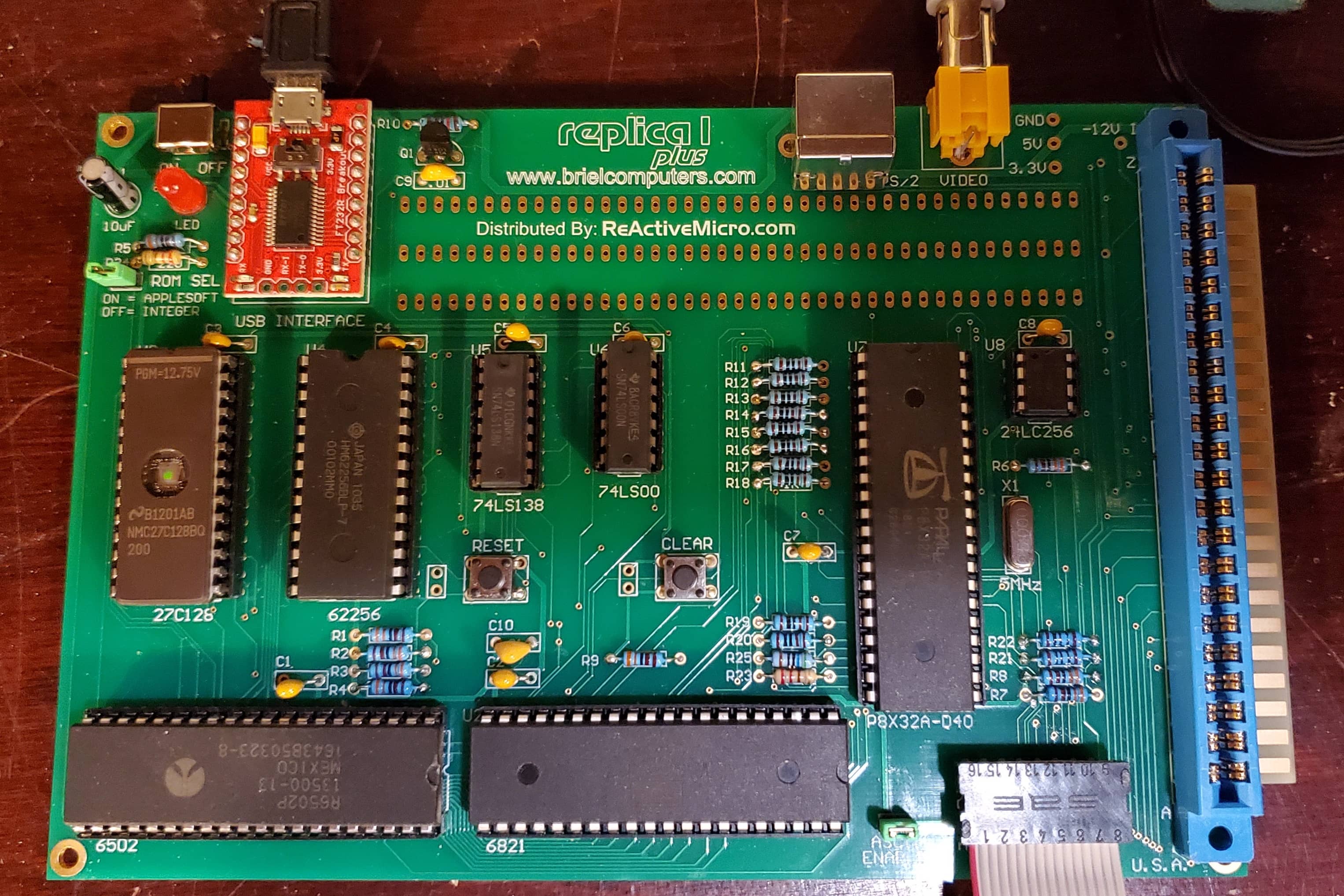
It seemed to be acting strangely after reset, producing extra carriage returns and @ symbols. After a few minutes it would calm down and start to behave normally. With him being new to the solder-it-yourself club, we suspected that he may have some poor soldering so I offered to have a look.
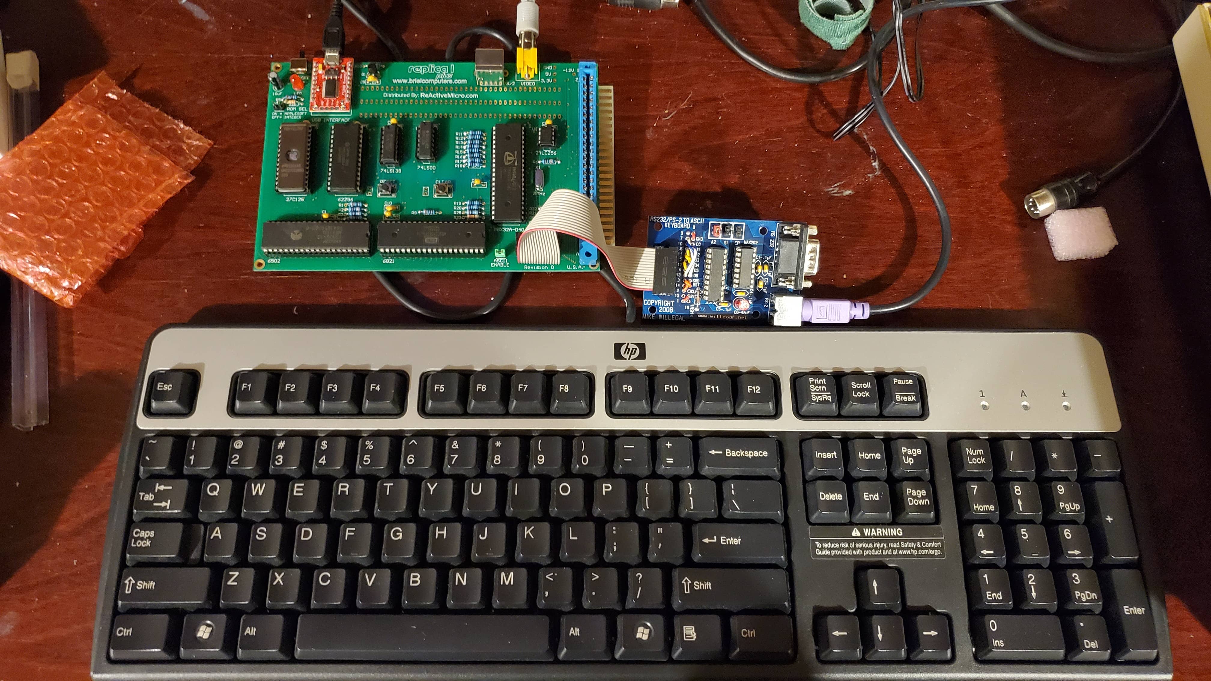
When he dropped if off a couple of days later, I plugged it in and everything seemed to be fine for me. It did look a bit rough on the bottom side, but I did not see any of the strange behavior that he had described. I tried my keyboard in the provided PS/2 port, as well as in the ASCII port with an adapter. There are some notes on the ReActive Micro wiki about how the Replica 1 can act like an antenna due to being powered by a PSU with an isolated ground, so I’m guessing it has to do with that. There are some fixes there we can try if this crops up again at least.
How about an ASCII Keyboard
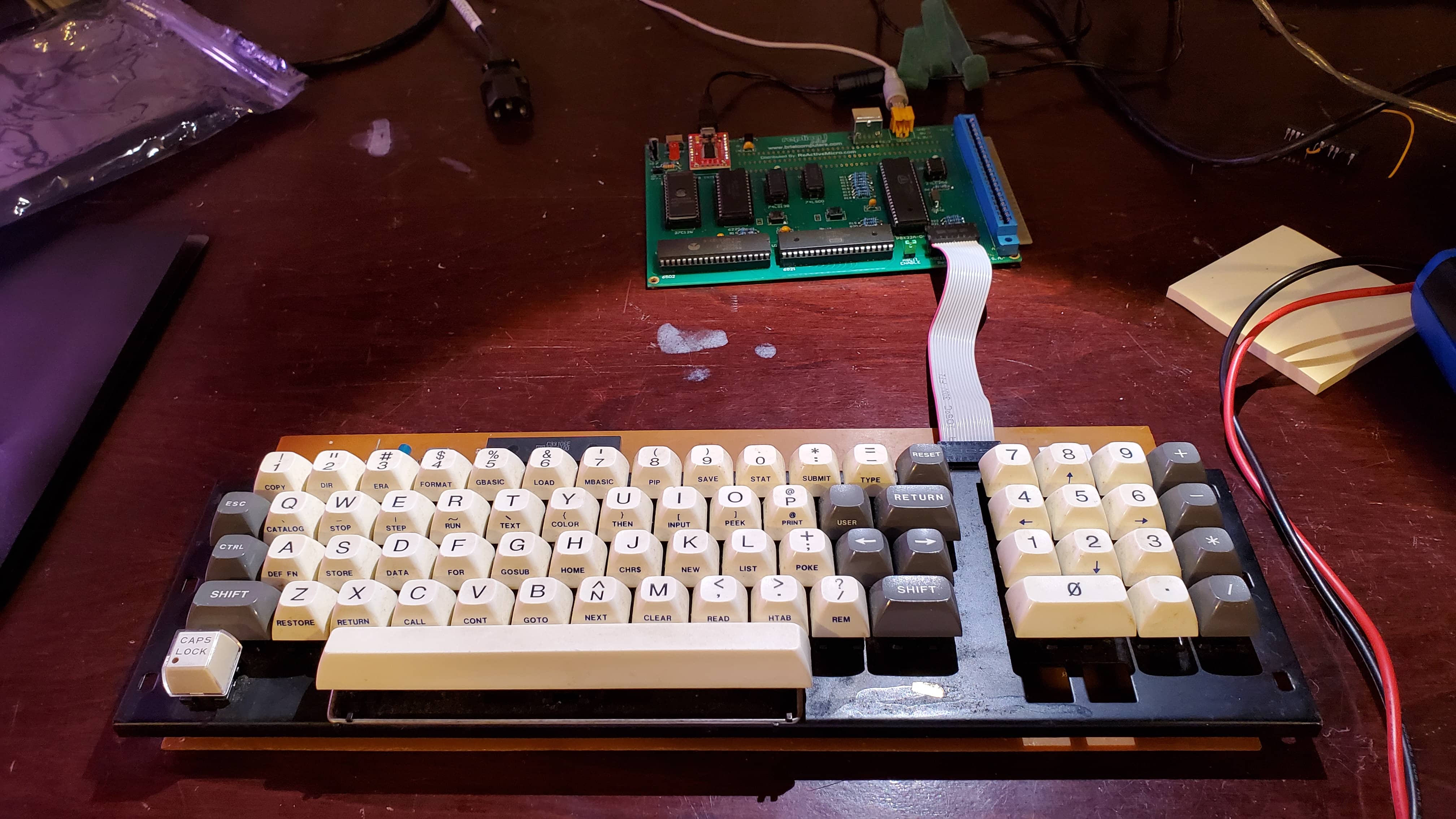
As his longer term goal is to have a custom case made up with a period correct keyboard, finding him a new PS/2 keyboard that would work didn’t seem worthwhile. We set out to find an old Apple II keyboard by asking around within our local retro computing community, and he managed to scare up a loose Apple II Clone keyboard that fit the bill. It looks great, and has a number pad to boot.
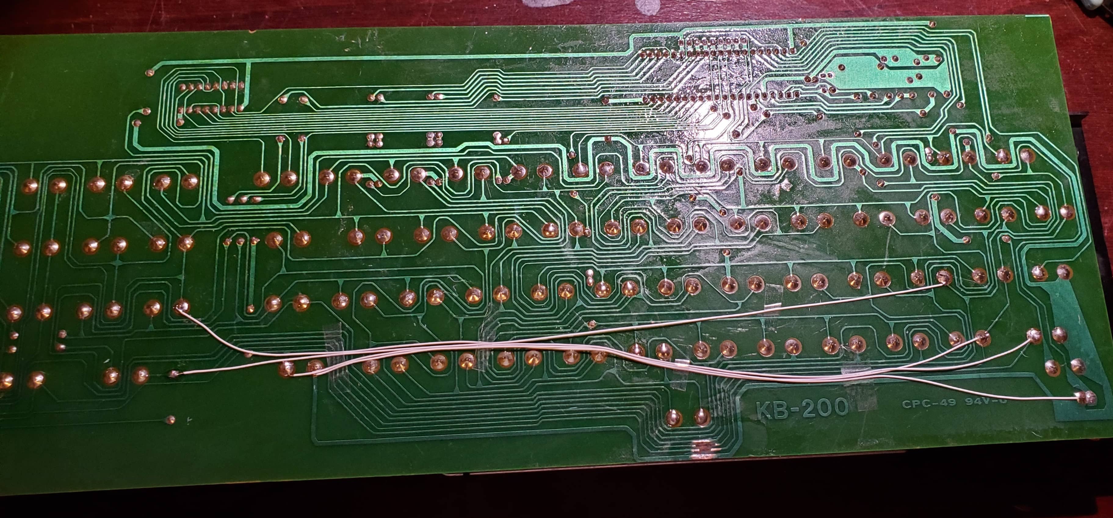
The keyboard arrived with a scratch through some of the traces on the bottom side of the PCB. I tried it with the Replica 1 anyway to see if there were any signs of life but, nothing was coming out of it at all. The POWER LED worked at least.
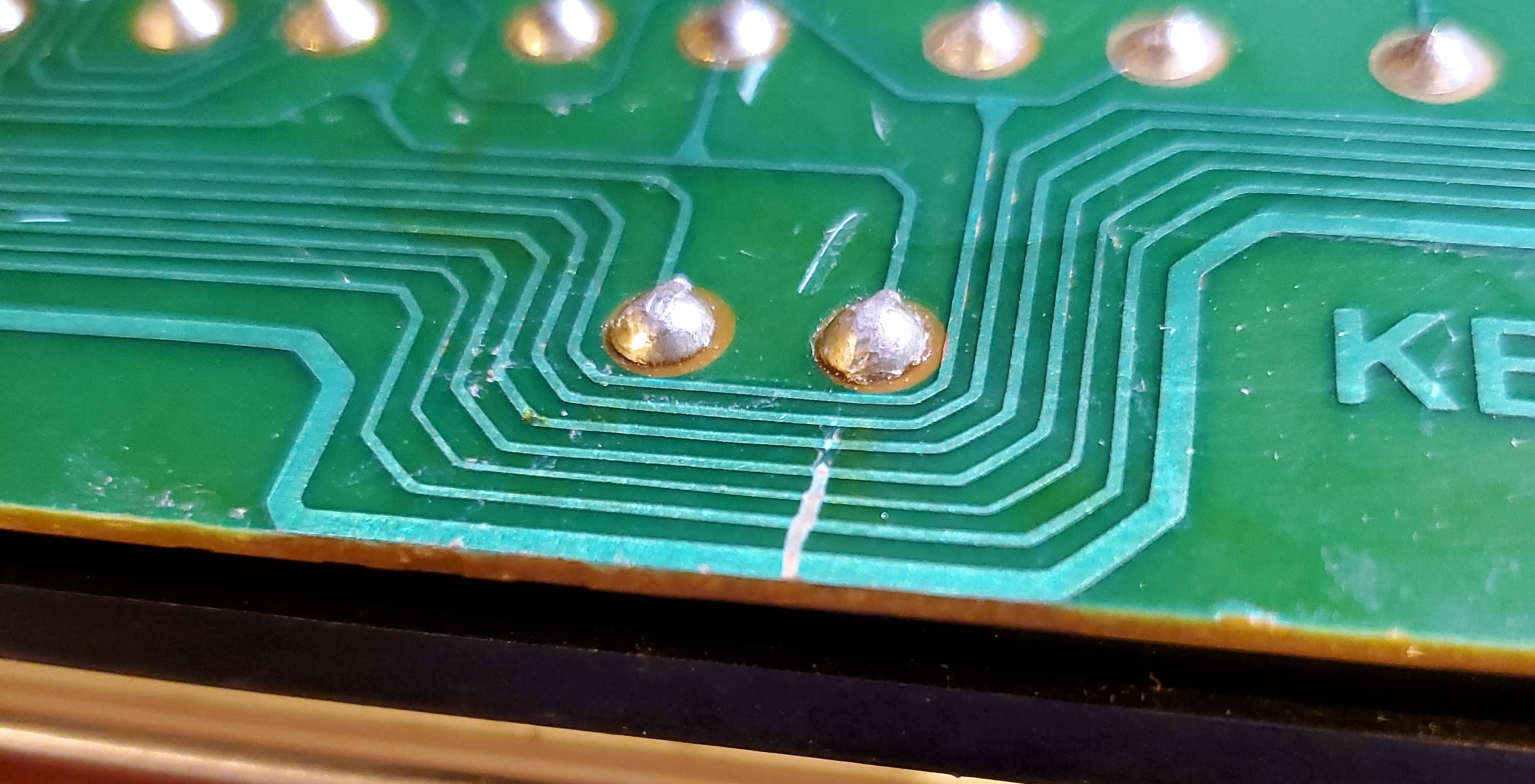
I scratched off some of the solder mask and added a couple of solder bodges, but I’ve since decided that this was a bad idea and I won’t be taking this approach going forward. While continuity was restored, I was not happy with the appearance of the repair and worse, the bits of wire and solder might catch on something and get torn off. We can’t have that so I removed it all and added some nice ‘taped down’ 30ga bodge wires.
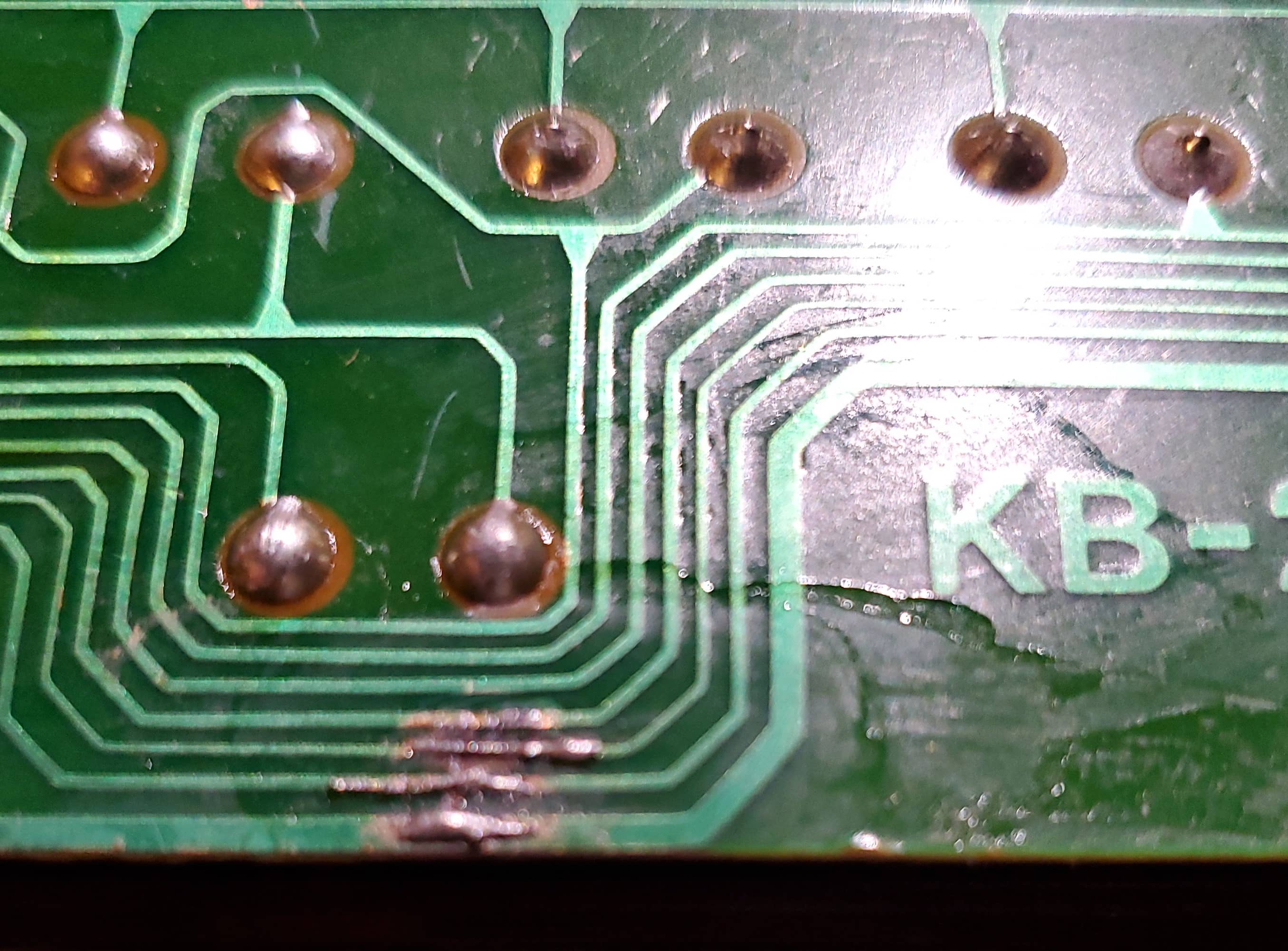
It clearly would have been much better to just leave the scratch alone. We’ll have to get some green nail polish on there now I guess.
It works! Kind of
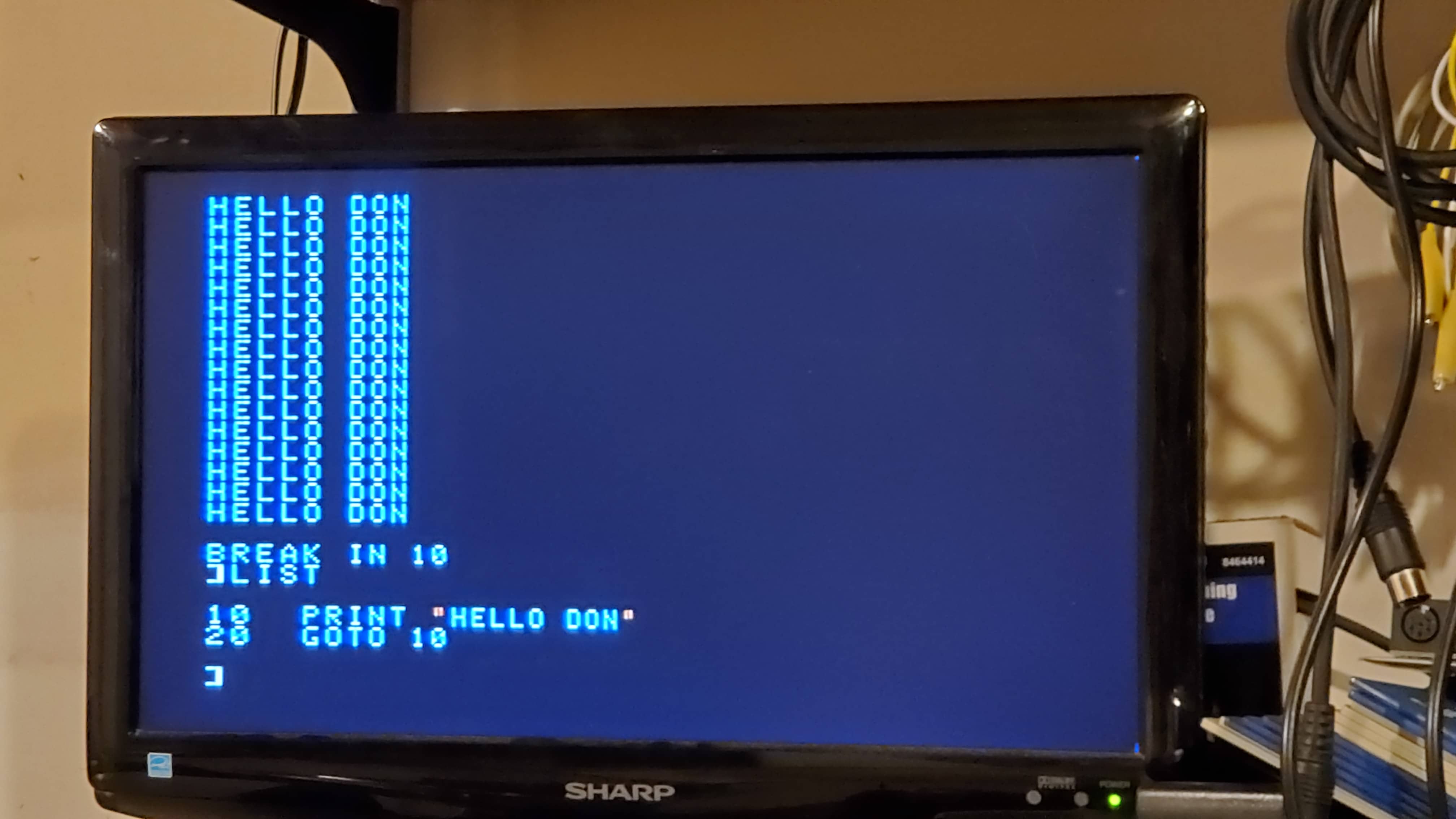
So I plug in the keyboard, press a few keys and still get nothing. I pressed the caps lock key, and now it seems to type great! However it becomes quickly apparent that the Replica One will not accept commands typed with these characters. I find if hold the SHIFT key that the correct characters type and managed to get to basic and type in a program.
Was this just a weird keyboard in a custom non-standard clone? (no) Were there more broken traces that I may have missed? (no). I borrowed the keyboard from my UNITRON to try out and it had a completely different problem! It seemed to type the correct codes, but would not ‘send’ the code until you had pressed a second key. It never catches up, in that you are always typing 1 key ahead of what you are seeing. My UNITRON keyboard has no keyboard controller, but instead has an EPROM and I suspect the strobe it generates does is not last quite long enough for the Replica 1. Just a guess.
I tried the repaired keyboard on my UNITRON and sure enough, it was behaving exactly the same as on the Replica 1. Something was certainly wrong with it still so I noted what ASCII values I was getting for each key.
The key I pressed is on the left, and the ASCII value returned in the various modes are in the columns extending out towards the right. I called lowercase mode CAPS, since to me it meant CAPS key was depressed.
KEY,NORMAL,NORMAL-SHIFT,CAPS,CAPS-SHIFT

A,1,65,97,65
B,2,66,98,66
C,3,67,99,67
D,4,68,100,68
E,5,69,101,69
F,6,70,102,70
G,7,71,103,71
H,8,72,104,72
I,9,91,105,73
J,10,74,106,74
K,11,75,107,75
L,12,76,108,76
M,13,77,109,77
N,14,94,110,78
O,15,93,111,79
P,16,ERR,112,80
Q,17,96,113,81
R,18,126,114,82
S,19,83,115,83
T,20,92,116,84
U,21,125,117,85
V,22,86,118,86
W,23,95,119,87
X,24,88,120,88
Y,25,123,121,89
Z,26,90,122,90
Well that can’t be good.
The controller appeared to be sending the correct keys when I held SHIFT while in lowercase mode. So A should be 65 since that is the value I got when I pressed SHIFT while in lowercase mode.
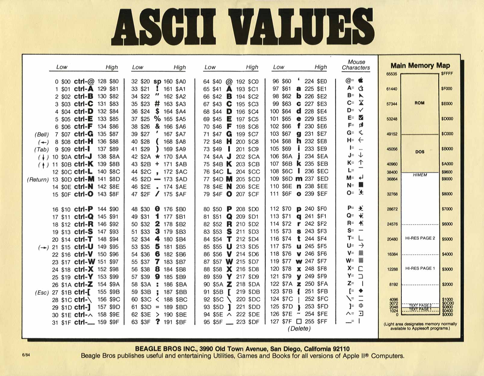
This wonderful ASCII chart I found confirms as much.
While using the GET function in basic, I also seemed to get the correct code while holding SHIFT in standard mode. I could not however, type this way to interact with the computer at all, and I’m kind of at a loss as to why. The only thing that seemed to be working was go to lowercase by depressing caps, hold SHIFT and then type the desired keys. You can imagine it is fairly awkward to type all your commands with SHIFT.
The other thing that was apparent after looking at the chart, was that the codes I was getting are the values for the CONTROL modifier pressed with each key. The keyboard seems to think CONTROL is pressed all the time!
I verified the control key wasn’t just stuck by checking for continuity. I ended up doing this for every key, and sure enough every key worked perfectly from a mechanical electrical switch point of view. I also followed the traces to the controller chip for the CONTROL key and was able to see it go from HIGH to LOW with a logic probe when pressed.
I went over the the back of the keyboard with a magnifying glass, but I could not find any more physical damage. Verified continutiy with the pin on the chip as well, and it was at this point when I accepted that the keyboard controller has probably failed internally. It’s going to think CONTROL is down at all times now while in upper case mode.
Ideas that didn’t work out
The first idea was why don’t we just find a new controller chip and be on our way… but as you might already know these keyboard controller chips are very hard to come by. Much harder than I had expected anyway. We were unable to source a replacement and it turns out the internet is littered with people looking for various keyboard controller chips and implementations of modern replacements. A whole new keyboard was an expensive proposition, so that was out too.
The next potential solution came from looking at the ASCII values in the chart. It appears that the value for A is 64 higher than the value for Ctrl-A. I attempted to direct the normally high line that the controller is supposed to use for Control, to the the D6 pin (7th bit) line on the keyboard connector but this just seemed to cause the controller to stop cooperating entirely.
Turns out no. I was unable to type at all while it was hooked up like this. Seems the controller doesn’t like that anyway.
EPROM Idea
I thought about this a little bit and thought hey, why don’t I just use an EPROM to output the ‘correct’ code when the ‘wrong’ code is presented. I can just feed strobe and reset lines straight though, then sit an EPROM in between the keyboard and Replica One.
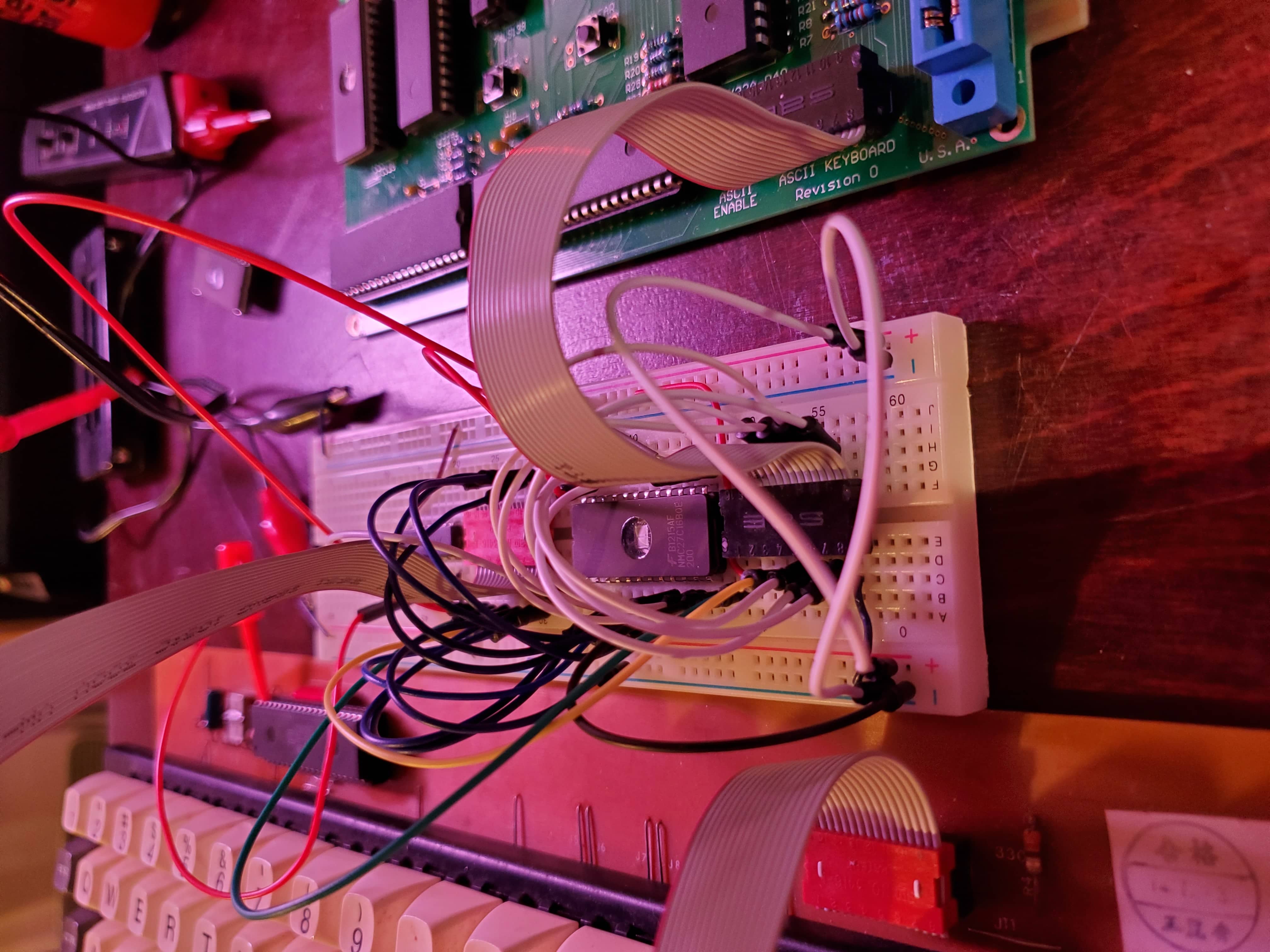
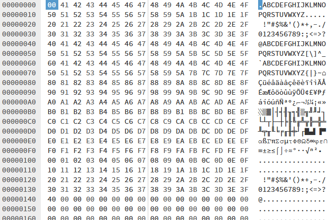
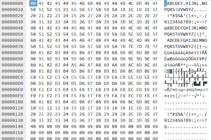
Here is the first try at the translation table/binary that I wrote to the EPROM.
I’m not sure why I entered anything above 00FF there, but it was late and this was my first burn. The keyboard has 7 data lines which I’m connecting to the address lines of the EPROM. I’m connecting the ‘CONTROL’ through pin 39 on the controller to an inverted to flip the 8th adddress pin HIGH on the eprom, sending us into the 128 to 255 range. Anything above 255 will not be accessed anyway, so no problem.
I was kind of surprised that when I plugged everything in, it actually kind of worked! It had not occurred to me that I needed to retain the ‘Ctrl-M’ value as that is actually RETURN. So while I could now type the letters without trouble, I could not press RETURN!
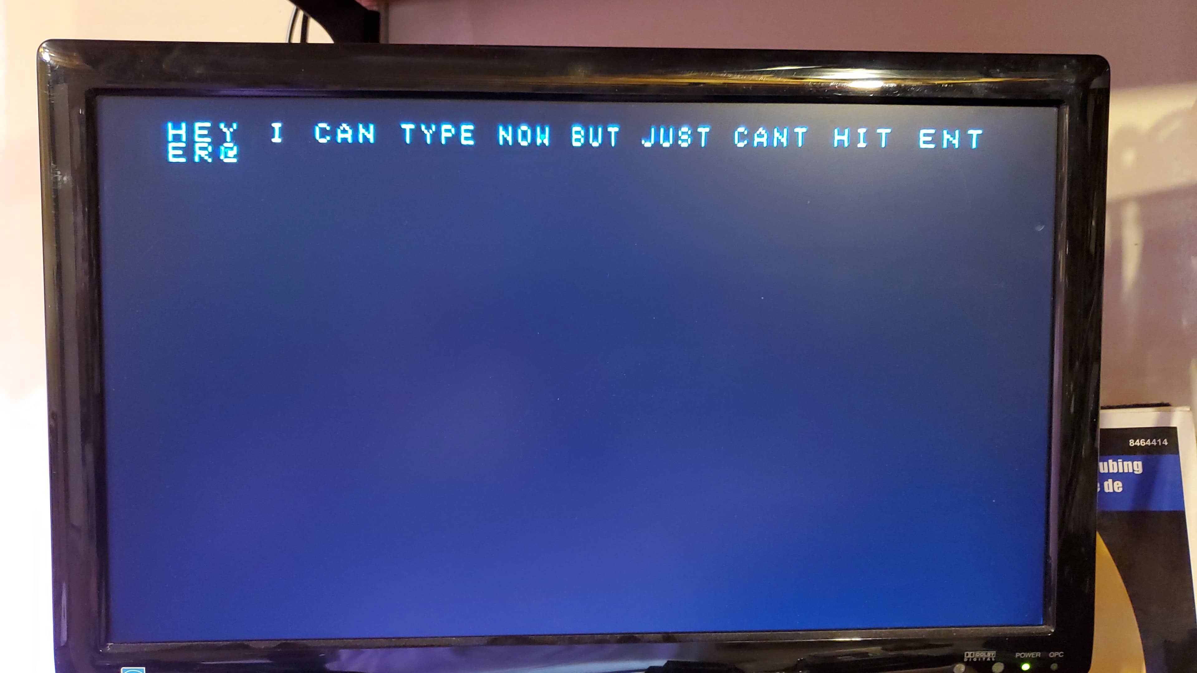
I made quick edit to the ROM contents to add ENTER (Actually RETURN) as well as the Left and Right arrows. I don’t think these arrow keys would work on the Replica 1, but at least if this gets plugged into an Apple II again it will be a little bit better off.
If this had not worked, another idea might have been to use a modern microcontroller to replace the failed controller, but this really sounded like a lot of work to me. I’m not even supposed to be here today!
So now what?
So technically, the keyboard remains broken. We can’t seem to find a replacement controller or correct the issue in place. My eprom translator setup is working well, but we can’t very well have a breadboard and a bunch of loose wires installed in the case with the computer. It probably would not survive long like that anyway.
I decided the thing to do was design a small PCB that would be able to be affixed to the back of the keyboard or be neatly installed in the case. I just jope the controller does not continue to degrade or develop new failure modes.
ASCIITRAN
If I was going to go to the trouble of making a custom PCB, I figured I should attempt to make the board sligthly more useful than simply to fix this one strange keyboard.
I imagined that there might be some other cases where you would want to have different characters available. Maybe your keyboard doesn’t type CAPS. Maybe you would much rather type on a DVORAK layout?
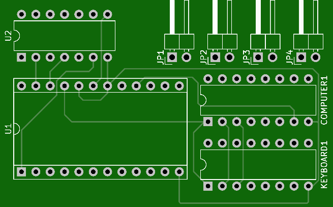
The smallest EPROMS I happened to have were 27c16 which left me with 4 extra address lines over and above what the keyboard would need, so I decided that these could be used for alternate modes or banks of translation tables. You are free to have the gerber files and make your own version of this but do so at your own risk, and you are on your own for the contents of the ROM. The ROM I burned is here in the incredibly unliekly event that you would have a keyboard with the same strange failuire mode that we ran into here.
By default, the inputs to the inverters on this board are to be tied to +5 with jumpers, which results in a 0 or LOW signal on the extra address lines and ensuring that we are at the beginning of the ROM address space.
On the keyboard we have here, the line coming off the CONTROL key is pulled high with a resistor to +5v, and is grounded when the CONTROL key is pressed. I’ve assumed that this is a similar setup for CAPS or other ‘modifier’ keys in general that one would add and thus I am expecting you would have a similar pulled high line, going to the input of JP1 that is grounded when you press your key.
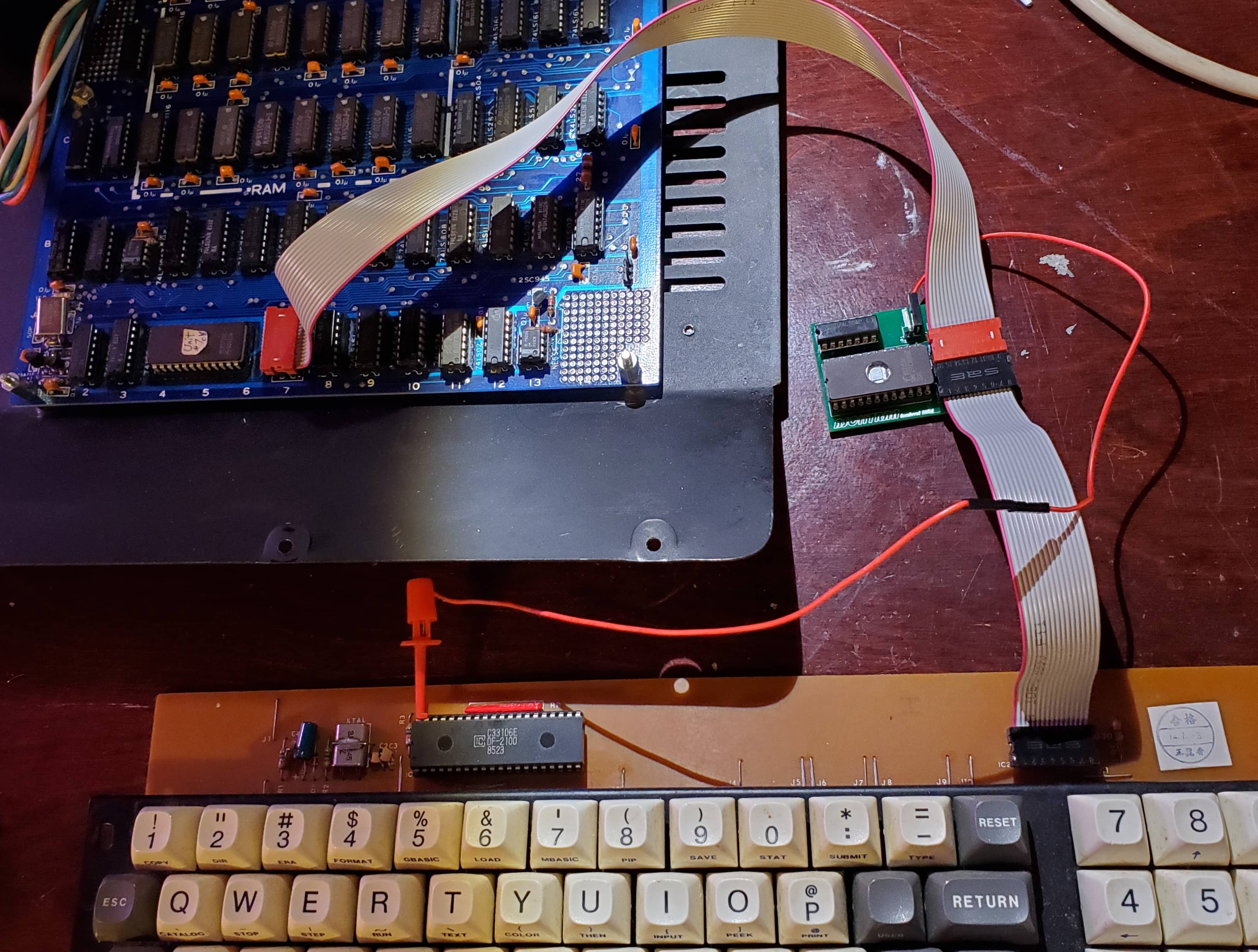
Success!!
I had the boards made up at PCBway, and they did a great job as usual. Here is it fully assembled and connected between the keyboard and my Apple II Clone. On to the next one!
Related Links
- lazilong.com / ASCII VALUES Beagle Bros Inc. ASCII VALUES Chart
- hexed.it - Web Hex Editor Web based HexEditor I used
- lowlevel.ca / Promenade C1 EPROM Programmer I used to write the new ROM.
- PCBWay.com / C64iSTANBUL Used this to test multiple basic ROM revisions…
- PCBWay.com / lowlevel ASCIITRAN PCB shared on PCBWAY!
Provided Here
- TRANS.BIN ASCIITRAN Rom for my friends keyboard fix. You probably want to make your own.
- ASCIITRAN Gerbers ASCIITRAN rev 1 gerbers if you don’t want to get them from PCBWay. (Dead link until I confirm they are correct.)
Todays soundtrack: