I recently obtained a Radio Shack TRS-80 MC-10 Micro Color Computer that I thought might be fun to play with. It was immediately clear to me however, that my new toy had a major design flaw. I found that I had to use my dominant hand to SHIFT and my not-dominant hand to type, while the mostly useless CONTROL key was in SHIFT’s spot mocking me.
This had to be addressed immediately.
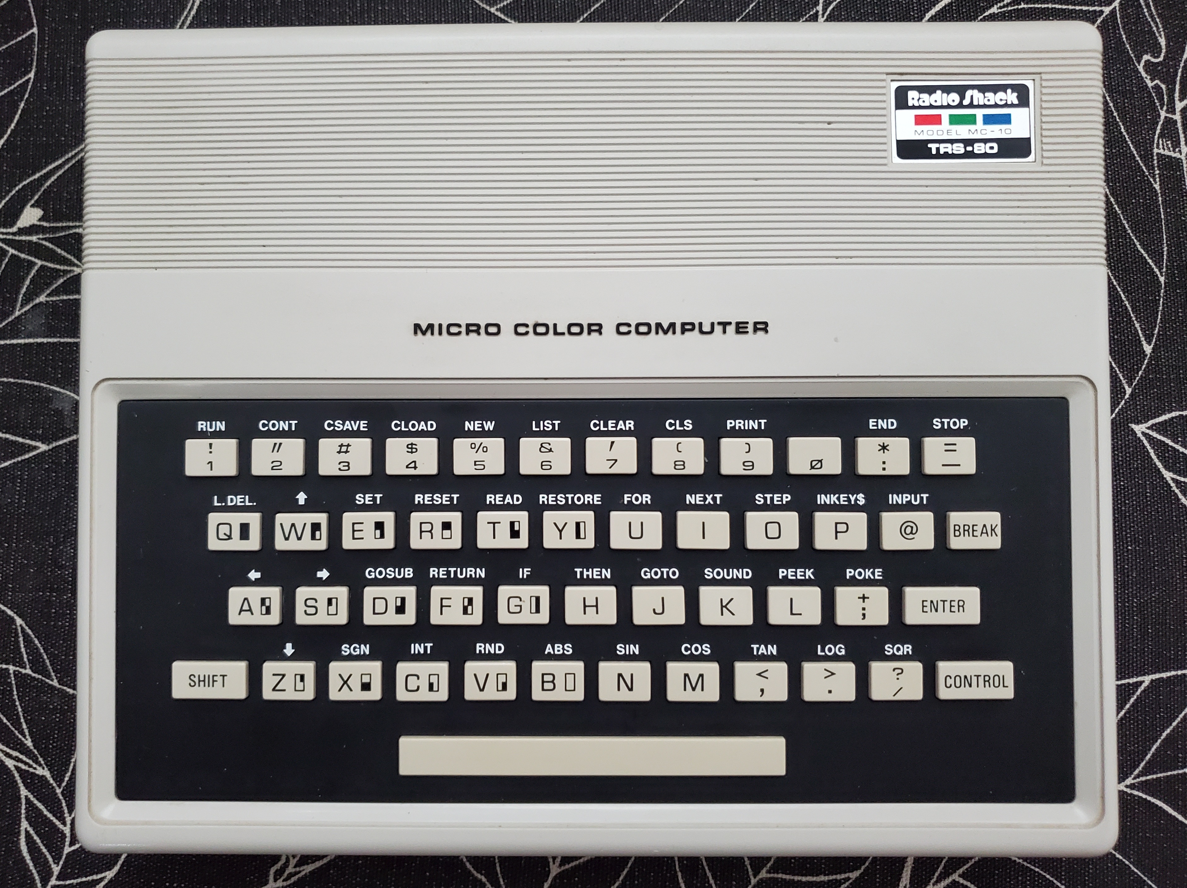
I opened it up to swap the keycaps thinking I could probably rewire the keyboard later… though I couldn’t help but appreciate how well this thing was built considering that it was launched as a budget minded computer. I was kind of expecting TS1000 redux, but we really have a lot more going on here. Colour, sound, individual key switches… and even a real PCB for the keyboard.
Approach
Hacking up the keyboard wiring certainly looked a little more complicated than I was originally thinking… and as you might imagine, I was really starting to like this computer.
Instead, why don’t I try to change the ROM in such a way that it thinks CONTROL is SHIFT and vice versa. I found this wonderful commented disassembly of the basic ROM by a Kevin Timmerman, which helped a lot here. A little bit of Ctrl-F (Find on Page) later, and I find this interesting sequence near a section that has comments referring to ‘Scan keyboard’:
(break key check is just above here)
LBLF8CD RTS                     ; End Scan Keyboard subroutine
LBLF8CE LDAA    #$7F        ; Port code for SHIFT key
LBLF8D0 STAA    ram02       ; Keyboard port i/o sequence
LBLF8D2 LDAA    ram03       ; A=0x00=found
        COMA                ; A=0xff=not found
        ANDA    #$02
        BEQ     LBLF8DB
        LDAA    #$FF
LBLF8DB RTS
LBLF8DC LDX     ram421D ;keyboard debounce delay
        JMP     LBLF861
LBLF8E2 STAB    ram02
LBLF8E4 LDAA    ioBFFF
        ORAA    #$C0
        RTS
LBLF8EA LDAB    #$F8
LBLF8EC ADDB    #$08
        LSRA
        BHS     LBLF8EC
        ADDB    ram4239  ; keyboard strobe store
        LDAA    #$FE     ; Port code for CONTROL key
I didn’t really take the time to fully understand what’s going on here before jumping in, but it looked to me like SHIFT and CONTROL are treated as modifiers, and the routine AND’s them with whatever other key was read. It occurred to me, that I can probably just switch these codes around.
Finding where to edit in the ROM
The disassembly of the ROM has some labels you might have noticed, indicating our ROM resides in the upper part of the 64k address space. Note that the labels in this section are in the F### range.
When we’re thinking about the ROM itself, addressing will start at 0000, and go to up to the highest address within it depending how large the ROM is. Our 8k ROM will go up to address 1FFF .
The ROM will be connected AT a 4k boundary somewhere in the memory map just due to the binary nature of how the addressing works. Eg: 0000, 1000, 2000… A000, B000, C000, etc. When we look at the disassembly and want to find the corresponding address in the ROM image, we just mentally subtract the starting offset from the address we’re interested in in to find our edit location.
eg. F8CF minus E000 is 18CF … which should be the location of the byte 7F we want to change.
So we find our 7F where we were looking for it… and not too far away we find the FE. The preceding two bytes are also seem to match the disassembly. In the second area (at 18F3) we see the last part of previously used ram address followed by what I assume is the opcode for LDAA(86). In the first one (just before our 18CF), it looks like we see LDAA again.. as expected… and the instruction before that was RTS. I’m going to assume the opcode for RTS is 39.
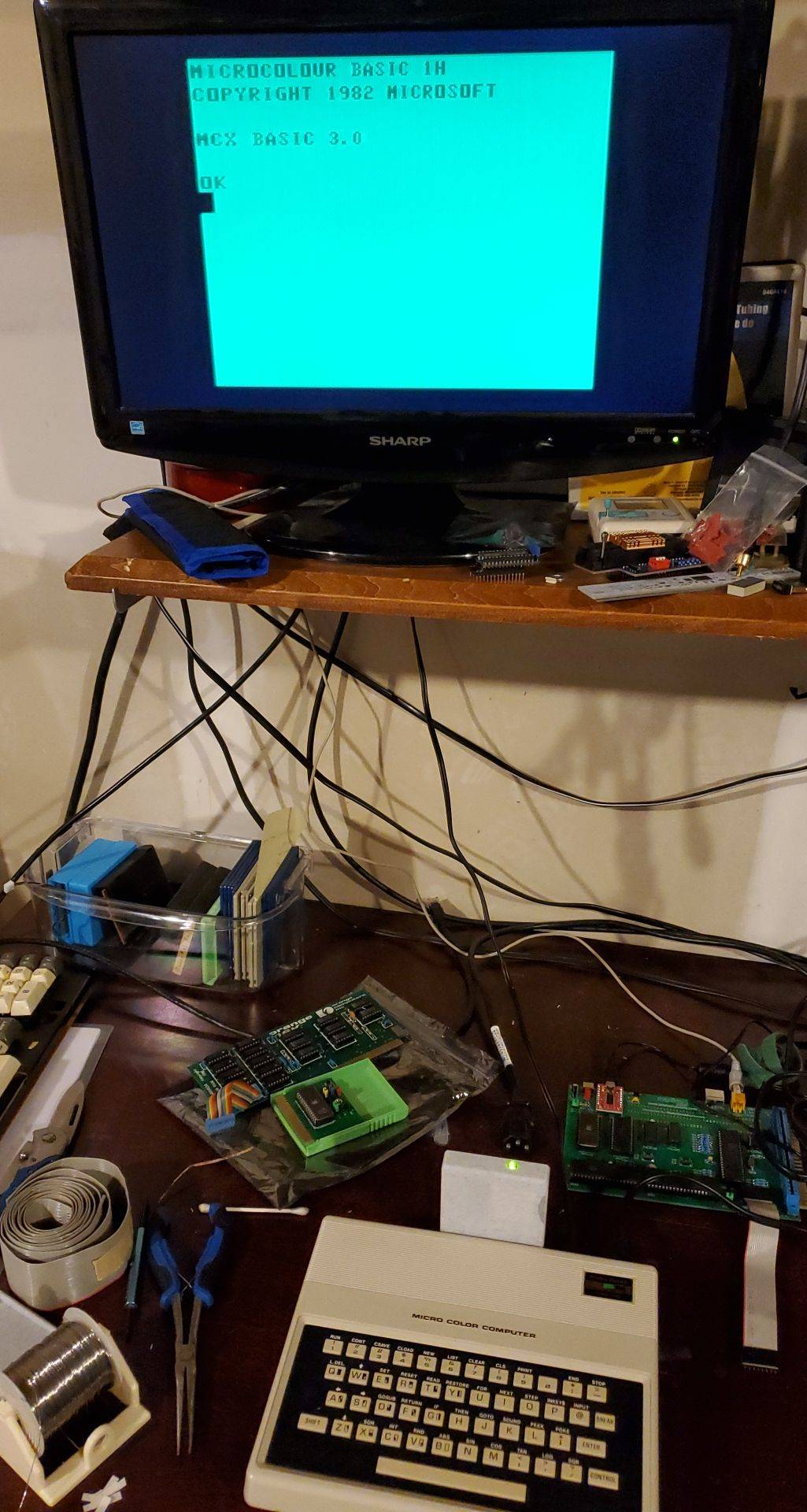
I decided to swap the two bytes and hope for the best. I also decided that I wanted to change the start up messages and version slightly so that I could easily verify if I was running the ROM later. Canadian optional.
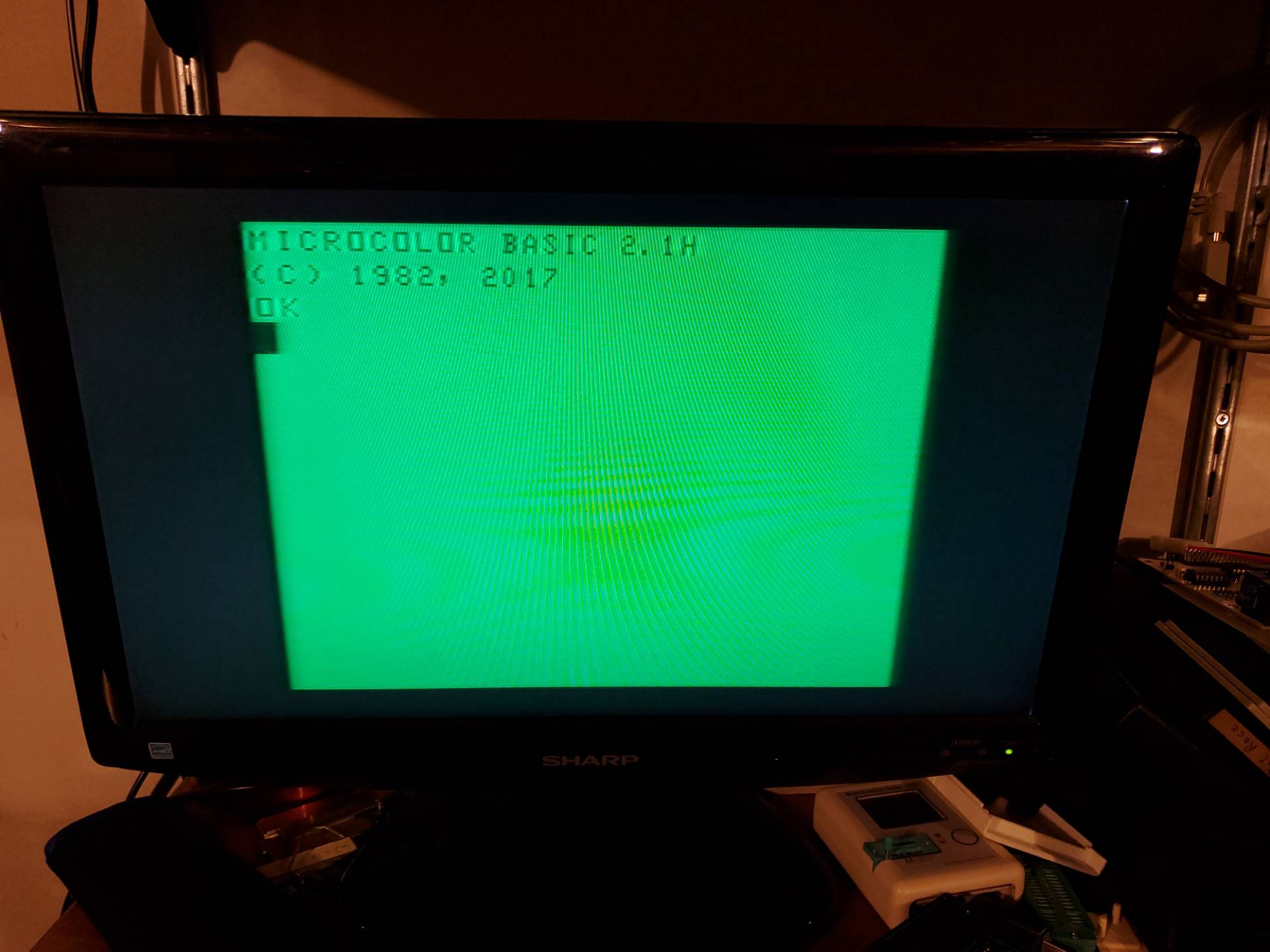
I saved the BIN file, and dropped it into an MC10 emulator… and wouldn’t you know, it worked exactly as I expected.
The CONTROL key now works as SHIFT and the SHIFT keys now work as CONTROL.
Success maybe?
Putting the ROM in the MC10
The MC10’s ROM is a TMS2564 type, which was is similar to the type in the Commodore line of computers so I figured I would use my kernal switch adapter and put 4 different 8k ROMs in my MC10!
I found the Matra Alice ROM, as well as an interesting ‘new’ ROM by a certain James Diffendaffer. I don’t know the status of this version (2.1c) however from what I gather, he has managed to pull off some speedups by optimizing some of the built in routines, and shedding some extraneous checking for break. Naturally this should be the ROM that goes in first!
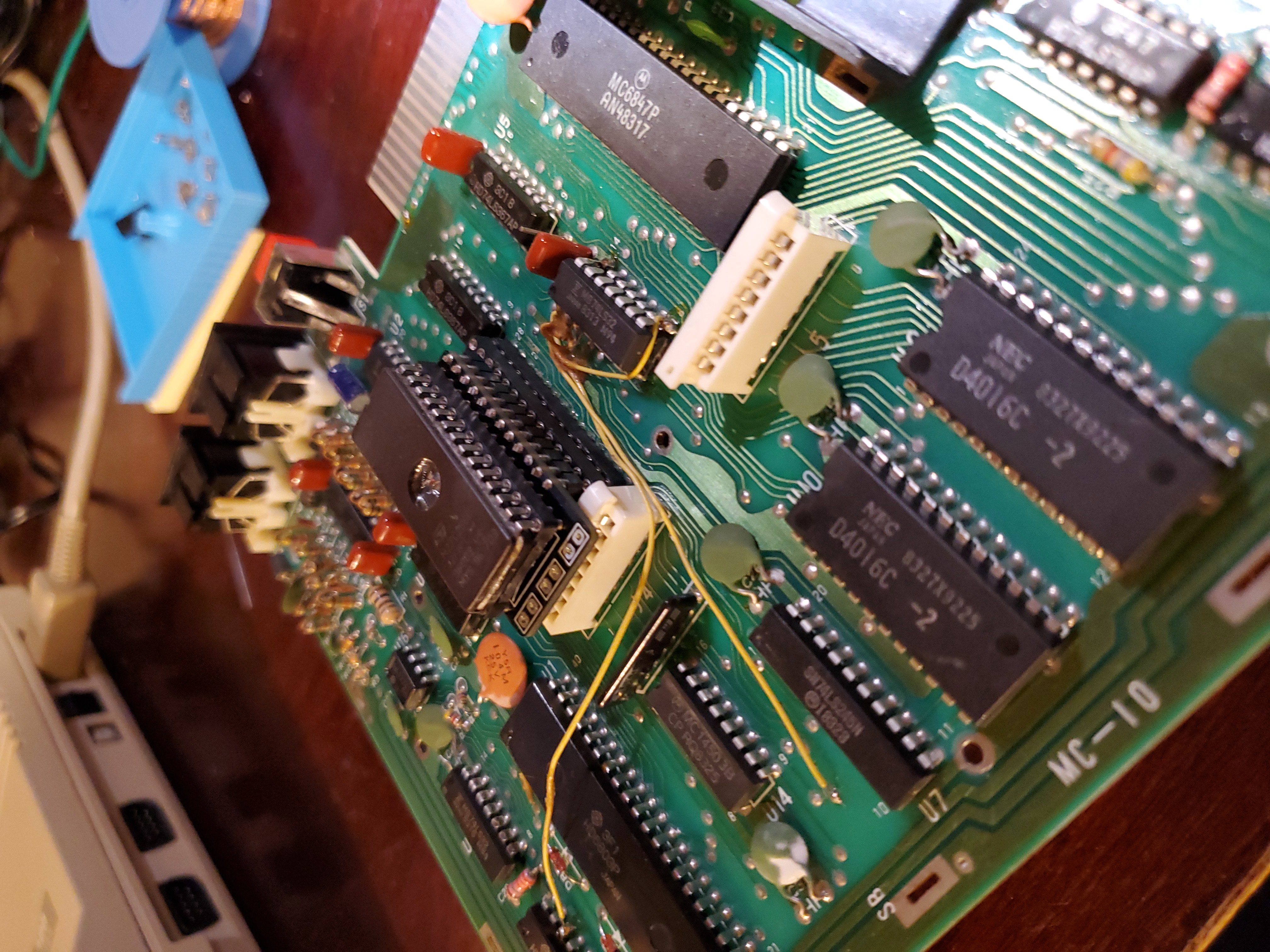
Here you can see that I had to use a bunch of sockets to get this particular c64 kernal switching adapter to clear the keyboard connector. Obviously I couldn’t leave this in here so I had to put some other adapter together later.

This is how it looks with the smaller adapter designed by Nicolas Welte This adapter is wired slightly different in regards to the CHIP ENABLE and OUTPUT ENABLE lines. I seemed to have to join them with a piece of jumper wire on this one (pin 20 to 22 on the 27c256), while they were already joined on the test one.
In this smaller adapter, I’ve currently just wired it to do the first bank resulting in having only JamesD’s 2.1c ROM. The shield has been cut for easy access to the ROM… and you can see I also added one of these beautiful composite adapters from The Zippster Zone
I had to remove a socket even after making the smaller adapter, as there not a lot of room with the keyboard hanging down and practically touching the metal shield when everything is buttoned up. I had a choice between losing the socket on the motherboard, or the socket on the adapter… I chose former so I could continue to remove and burn different stuff onto the ROM.
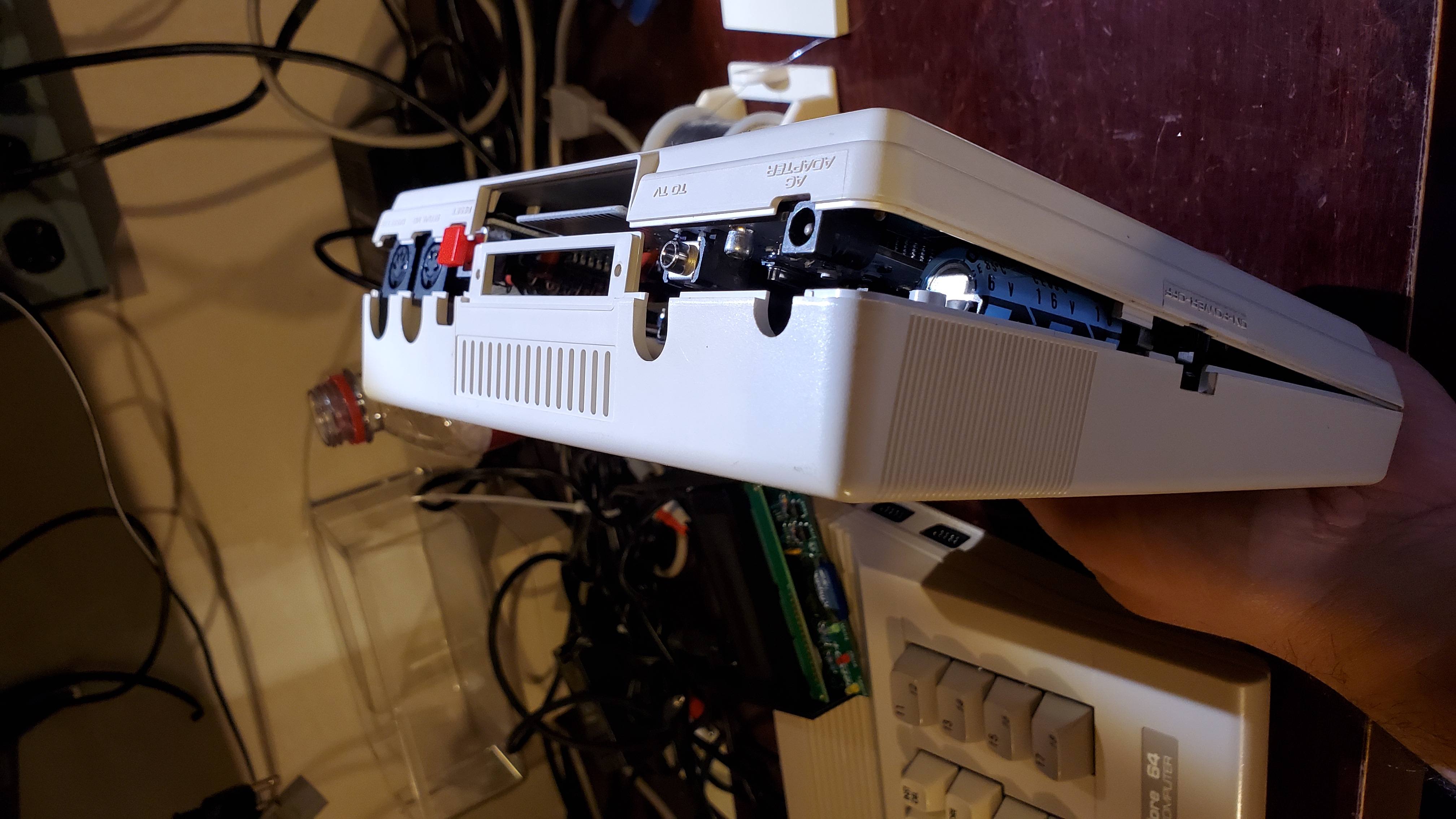
This is as closed as I could get the case with the socket on the motherboard still.
Another Approach
I also thought I might try to put the modified ROM in my MCX32-SD and skip the whole ruining my computer part, but it seems there isn’t a documented way to switch ROMs currently. So far I have been unable to figure out how to do this from the computer as I would have expected to be able to do.
I was however able to remove the EPROM from the MCX32-SD to read edit and reprogram but I don’t recommend this as you’re probably on your own if anything goes wrong…
I will say that the MCX32-SD is a very nicely made peripheral, and I’m super impressed with the quality of the soldering and included 3d printed case. I’m hopeful that the instructions or capability to switch ROMs on the MCX32-SD will come in the future.
Reference Material
- trs-80.com / Ira Goldclang MC-10 Overview
- colorcomputerarchive.com MC-10 Service Manual
- ManualsLib.com MC-10 Service Manual
Related Links
- hexed.it - Web Hex Editor Web based HexEditor I used
- lowlevel.ca / Promenade C1 EPROM Programmer I used to write the new ROM.
- vic-20.de / Flash/RPROM Adapter Used this to install ROM in MC-10.
- PCBWay.com / C64iSTANBUL Used this to test multiple basic ROM revisions…
- PCBWay.com / Retrotinker Suspect this would do the trick but did not try.
- jdiffendaffer.blogspot.com / What good is a new MC-10 Rom?
- mcxwares.blogspot.com / MCX32-SD
- thezippsterzone.com / MC10 Items For Sale
Provided Here
- MC10 Rom 1H.BIN Control/Shift Swapped MC-10 Basic 1.0
- BURN.BIN 27c256 image with 4 basics, Control/Shift swapped on first 3 probably.
- NEWMCX32.BIN MCX32-SD EEPROM/Flash image with Control/Shift swapped for the main MC10 basic. (please be careful)
Todays soundtrack:
