The Compy2600 came about as an effort to clean up a rather ugly AV mod I was asked to fix in a friends Atari 2600. I designed it to plug in in place of the existing RF modulator can, but you can also install it with wires should you want to leave the RF can in there for the future.
I think this is a fairly common mod that has been known for several years. There are some components you can optionally cut out or remove as well to improve the video quality. I am quite happy with the results, however you might want to look at the Ultimate Atari Video if you’re looking for the best solution.
There were serveral Atari 2600 PCB’s over their very long and storied production run, so you may have to do some investigating if your model differs significantly from mine or any of the ones I’ve managed to cover here.
Typical Components
| Qty | Part | Description |
|---|---|---|
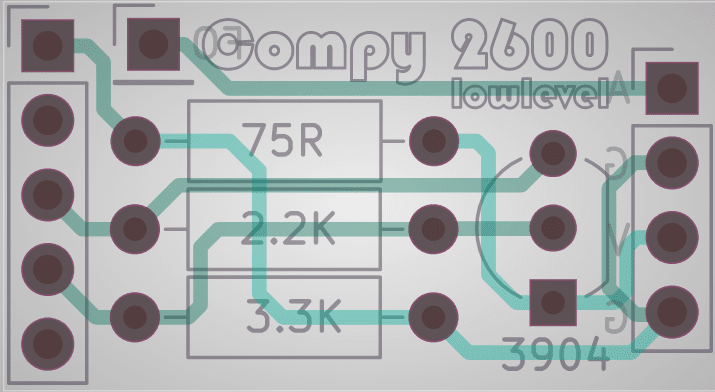
| 1 | PCB | Compy 2600 printed circuit board |
| 1 | CFR-25JB-52-75R | 75 ohm 1/4 watt resistor |
| 1 | CFR-25JB-2K2 | 2.2k ohm 1/4 watt resistor |
| 1 | CFR-25JB-52-3L3 | 3.3k ohm 1/4 watt resistor |
| 1 | 2N3904-AP | 2N3904 General Purpose NPN Transistor |
| 1 | M20-9960545 | 2.54mm pitch Right Angle Header Male |
| 1 | RCJ-033 | Optional Panel Mount RCA Jack White (audio) |
| 1 | RCJ-034 | Optional Panel Mount RCA Jack Yellow (video) |
| 1 | Misc | Optional pre-made a/v cable, or some sheilded audio cable if using RCA jacks. |
| 1 | Misc | Length of single conductor hookup wire (about 4” long) |
As listed, you will need some wire or optional connectors/headers if you want the a/v cables easily removable later. I like to use sheilded audio wire but I haven’t noticed any problems using standard hookup wire. You will also need a single hookup wire for the audio as we don’t take it from where the RF modulator got it.
Optionally, use a standard pre-made AV cable in place of the panel mount jacks if you would rather run the wire out the back instead of drilling holes in your Atari. I like this option.
Procedure
Assemble the PCB first so if you make a mess of it, you can still give up.
Turn off the Atari and unplug everything.
Remove the screws from the bottom of the unit and carefully separate the bottom from the top.
Remove the main board from the Atari. There are some foam pads on the switch stems that will fall off if you turn the board upside down. Don’t lose them.
Separate the metal sheilding from the main PCB. There will be tabs on the bottom side you have to flatten with pliars to release the two peices.
If you’re going to drill holes for the A/V connectors, you should do that now. You can place them in the bottom shell. Center or off to one side if up to you. Just make sure they will not interfere with anything when back together. The connectors I found require a 1/4” hole.
Solder your wires on to the connectors and install them in the bottom shell. Put the center wire to the tip if you are using sheilded wire.
Desolder the RF can and it’s 5 pins going to the main board. (Be patient, this is probably the hardest part of the project.)
Solder the Compy2600 mod in place as show. The component side should face forward. (Refer to pictures.)
Place the Atari main PCB in the bottom shell, with the installed connectors and wires. You will bring these over to the Compy2600 and trim/solder them there.There are four pads at the top of the Compy2600 for this. These are labeled at the back as A (audio) and V (video) along with a G (ground) for each. G and V on the right go to your Yellow RCA connector. And A and G on the left go to your White RCA connector. Leave yourself at least an inch or two of slack incase you have to re-do any of this in the future.
Solder the Audio flyout wire (Labelled FO on the back of the Compy2600) to the appropriate place on your Atari PCB. (Refer to pictures.)
Audio Flyout and Optional Component Removal
I think the audio is on the right most pin of the RF modulator, but something happens to it before it gets there that makes it kind of unusable for an audio out. Because of this, we have to pick up the audio elsewhere. This may be different depending on your board, so I will try to add to this list as I find more revisions. Try to find the COXXXXXX number or go by what you see as a visual match.
There are also some parts you can remove or cut out to improve the video signal. You can cut one leg and bend the component up, or simply desolder and remove entirely. I found these optional cuts or removals to be worth doing, but if you think you will want to put the RF can back in at somepoint, you can skip this.
The part reference labels are often under the part or obscurred so you can use the picture to help locate them. Again, I will post new pictures if I encounter different boards.
CO15519 Rev 14
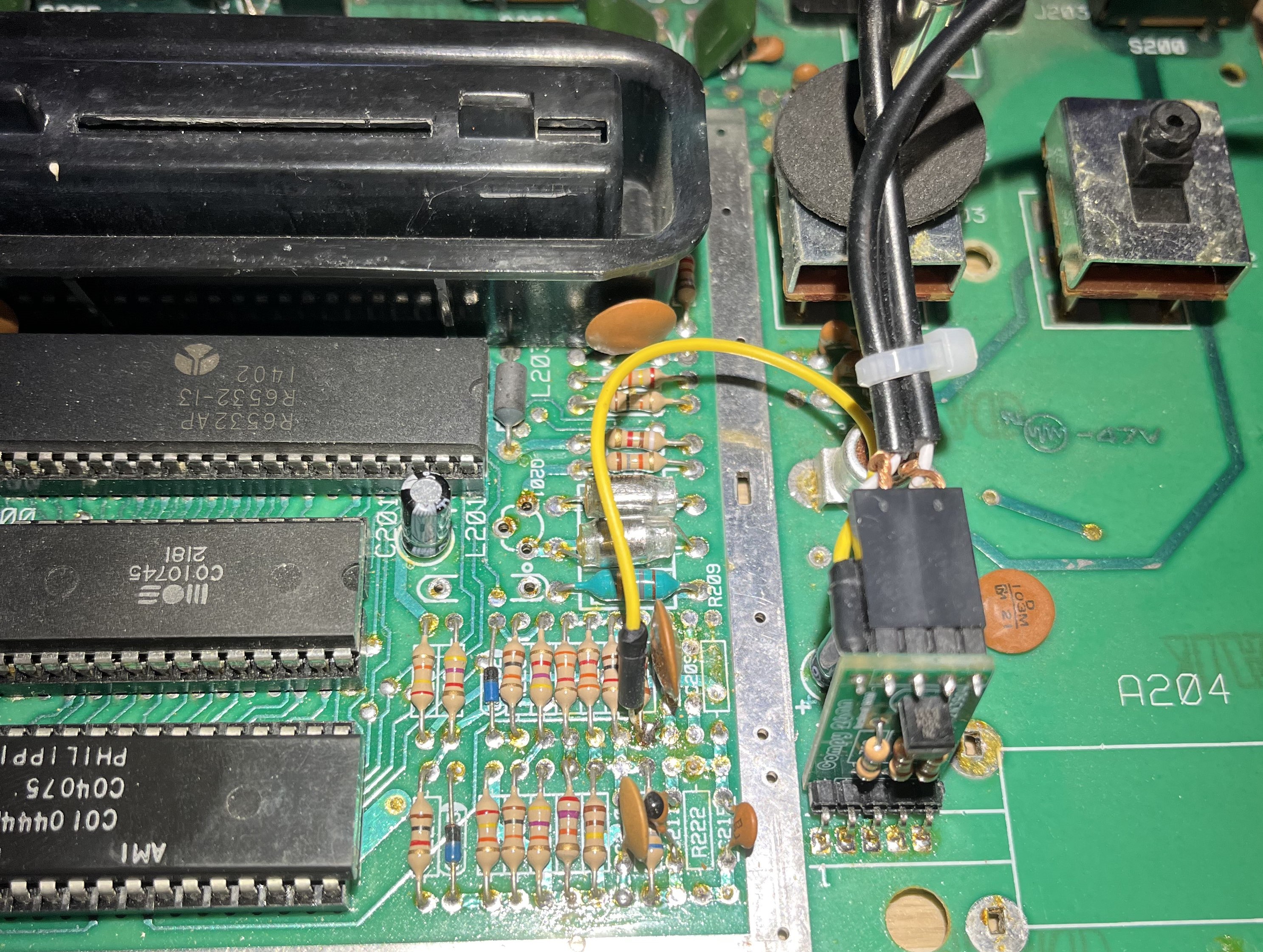 Pick up Audio on the forward end of the resistor just behind C208 or C208. (bridged here)
Remove Transistor Q201 (Optional)
Remove Reistor R209 and R222 (Optional)
Remove Capacitor C205 (Optional)
I removed L201, since it was damaged on mine. (Tall/red tunable inductor coil)
Related Links
Provided Here
Todays soundtrack: