The Bwack C64 Saver is a device you put between the Commodore 64 and it's power supply to prevent damage to sensitve electronics in the event of a power supply failure.
If you've decided to purchase a vintage Commodore 64 as of late, no doubt you have run into everyone and their brother warning of the potential for the powersupply to fail in such a way that will destroy the computer.
The typical epoxy filled brick that Commodore was supplying with their computers supplied two voltages. AC at around 9-11volts, and regulated DC at 5 volts. The 5 volt regulator in these power supplies tends to fail in such a way that the voltage feeding it might be passed through, damaging sensitve 5 volt integrated circuits. Commodore started filling the power supplies with epxoy which probablh didn't help.
The Thing
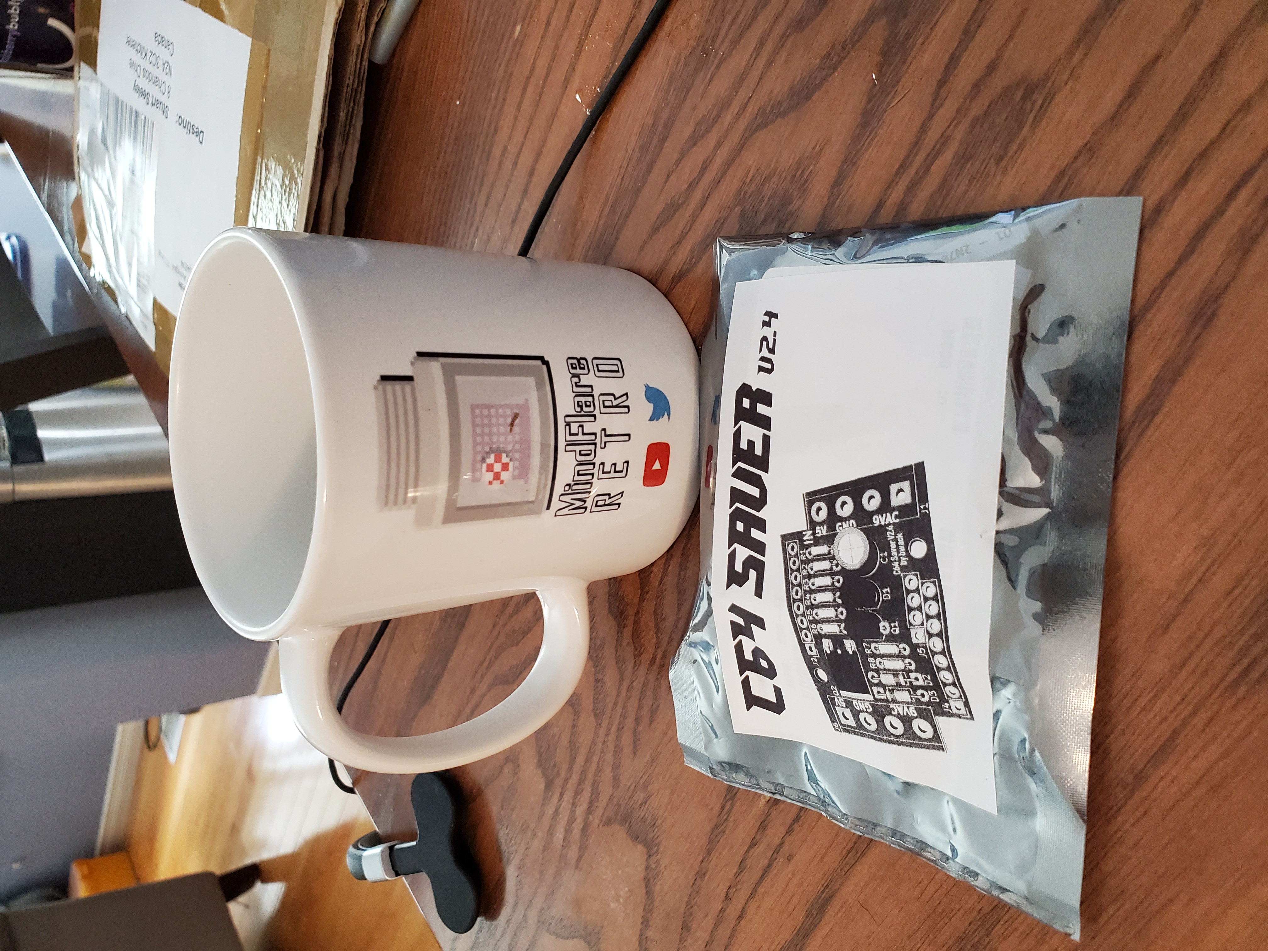
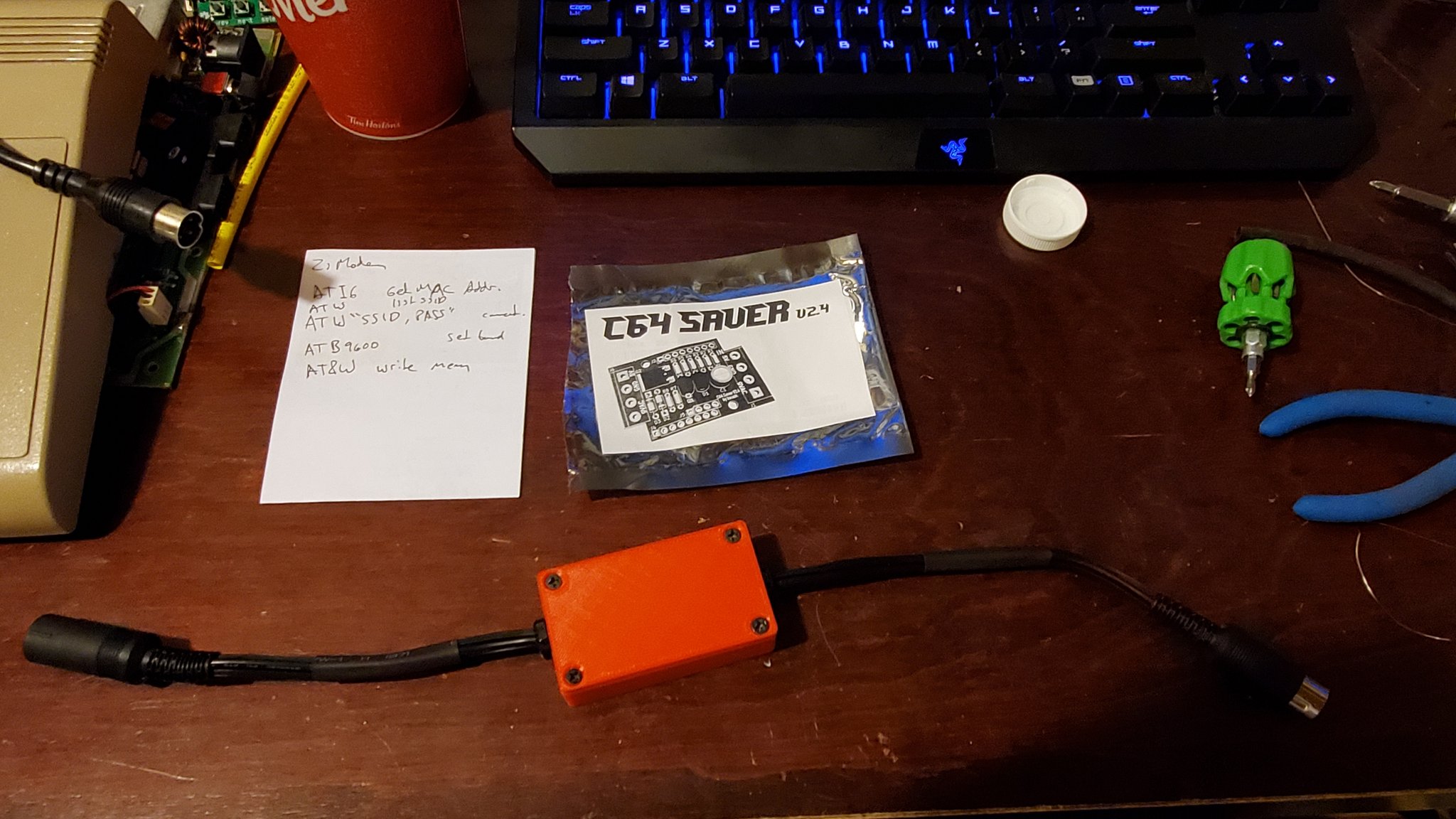
The BWACK C64 Saver is an open source project. You can optionally have the boards made up yourself and order all the parts. I was lucky to receive a free PCB and a spiffy coffee mug from Mark at MindFlareRetro whom I had the pleasure of meeting at one of the local retro computing meet ups... so I will be building that. Thank you Mark!
Parts List
Here is the parts list if you happen to be sourcing them yourself. I was lucky to get everything but the enclosure in the box.
| Ref | Description | Part |
|---|---|---|
| R1,R6 | 3.9k Resistor | RNMF14FTC3K90 |
| R2,R3,R5 | 3.3k Resistor | RNMF14FTC3K30 |
| R4 | 330k Resistor | RNV14FAL330K |
| R7 | 33k Resistor | RNMF14FTC33K0 |
| R8 | 82k Resistor | RNMF14FTC82K0 |
| C1 | 47uF Electrolytic Capacitor | 25ML47MEFC6.3X5 |
| D1 | TL431LP Diode | TL431BILPG |
| D2,D3 | 1N5235B-TR Zener Diode | 1N5235B-TR |
| Q1 | 2N7000 TO-92 N 60V Transistor | 2N7000-D26Z |
| Q2 | IRFR5305 SMD DPAK Mosfet | IRFR5305TRPBF |
| BOX | Hammond 50mmx35mm Project Box | 1551GBK (BK Black) |
| CN1 | 8 DIN Female | 12345 |
| CN2 | 8 DIN Male | 12345 |
| MISC | Short lenghts of wire |
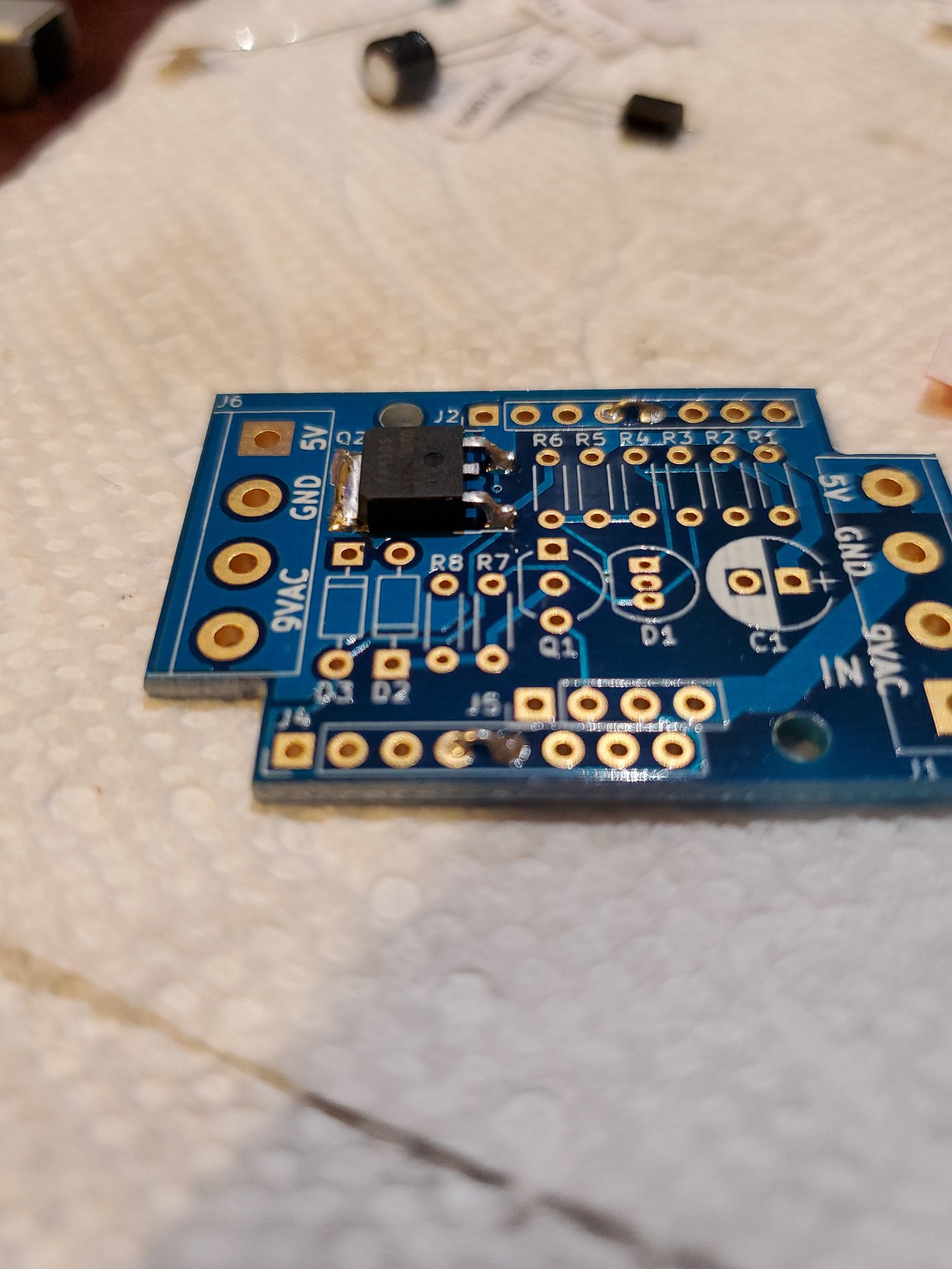
Assembly
Start with the surface mount regulator first. I chose to place solder on the board first, heat that up and plop the part into the molten solder so as to not be cooking the regulator. I think they are pretty robust though, so hopefully you don't damage it however you choose to solder it. There is an optional software control/display 'addon' board, that if you're not using you solder 2 jumpers as you can see here.
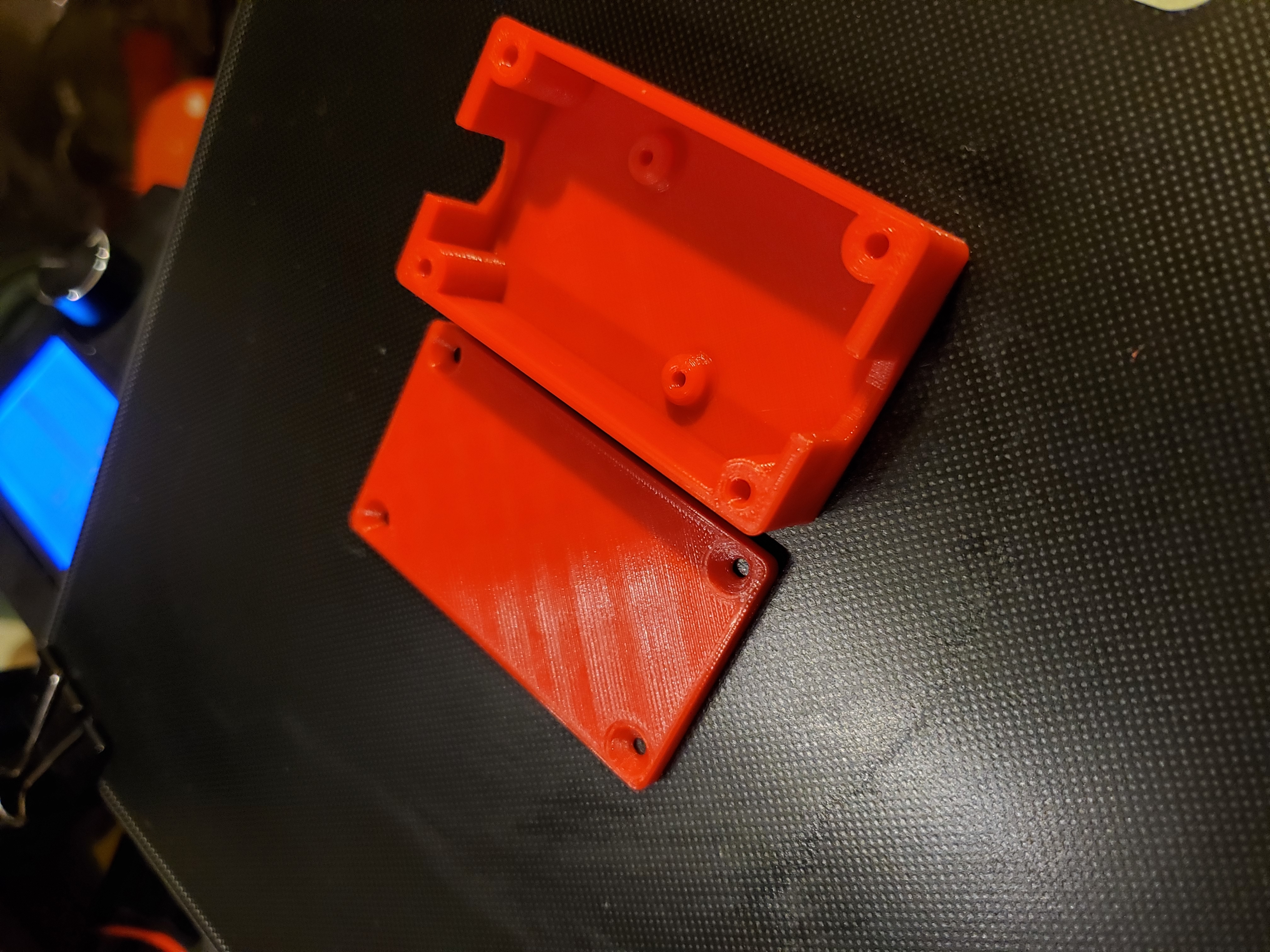
The project is designed to fit in a project case produced by Hammond, but there is also a 3D printable case if you're into that. I am pretty happy with the printed case. I think the 1551 box is a little smaller, and this 3d printed one is based on a different slightly longer version, so pay some attention to which you select if you're buying one.
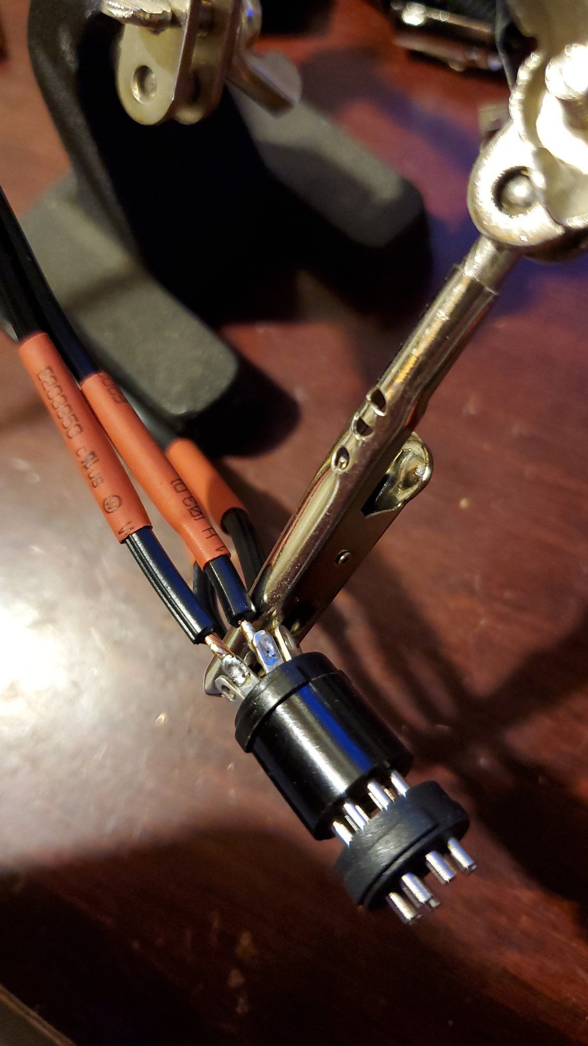
You can insert the male end into the female end to prevent any pins from moving as you heat them up. Soldering DIN connectors is probably one of my least favorite things, but take you time and double check you have the right pin... or triple check. I manage to screw it up almost everytime.
You will want some pretty decent wire for the cable ends. I used cut off ends of an Atari XL power supply, which incidently enough is also not to be trusted for exactly the same reason as the Commodore 64 brick.
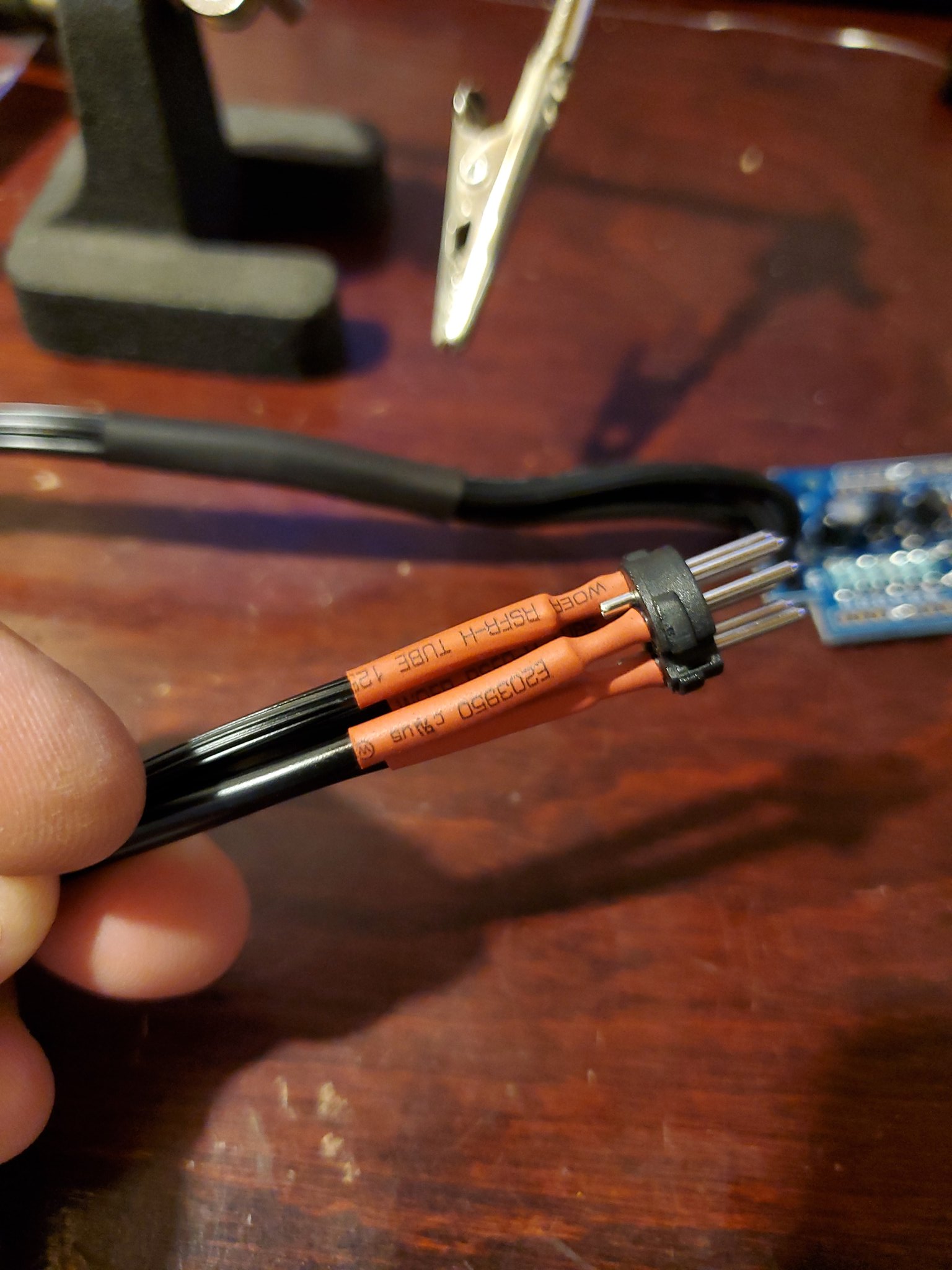
Your wire should be stranded, but make sure all the strands get through the holes and there are none sticking out anywhere to cause a short. You can optionally use 'ferrels' to avoid this issue, but that's too rich for my blood.
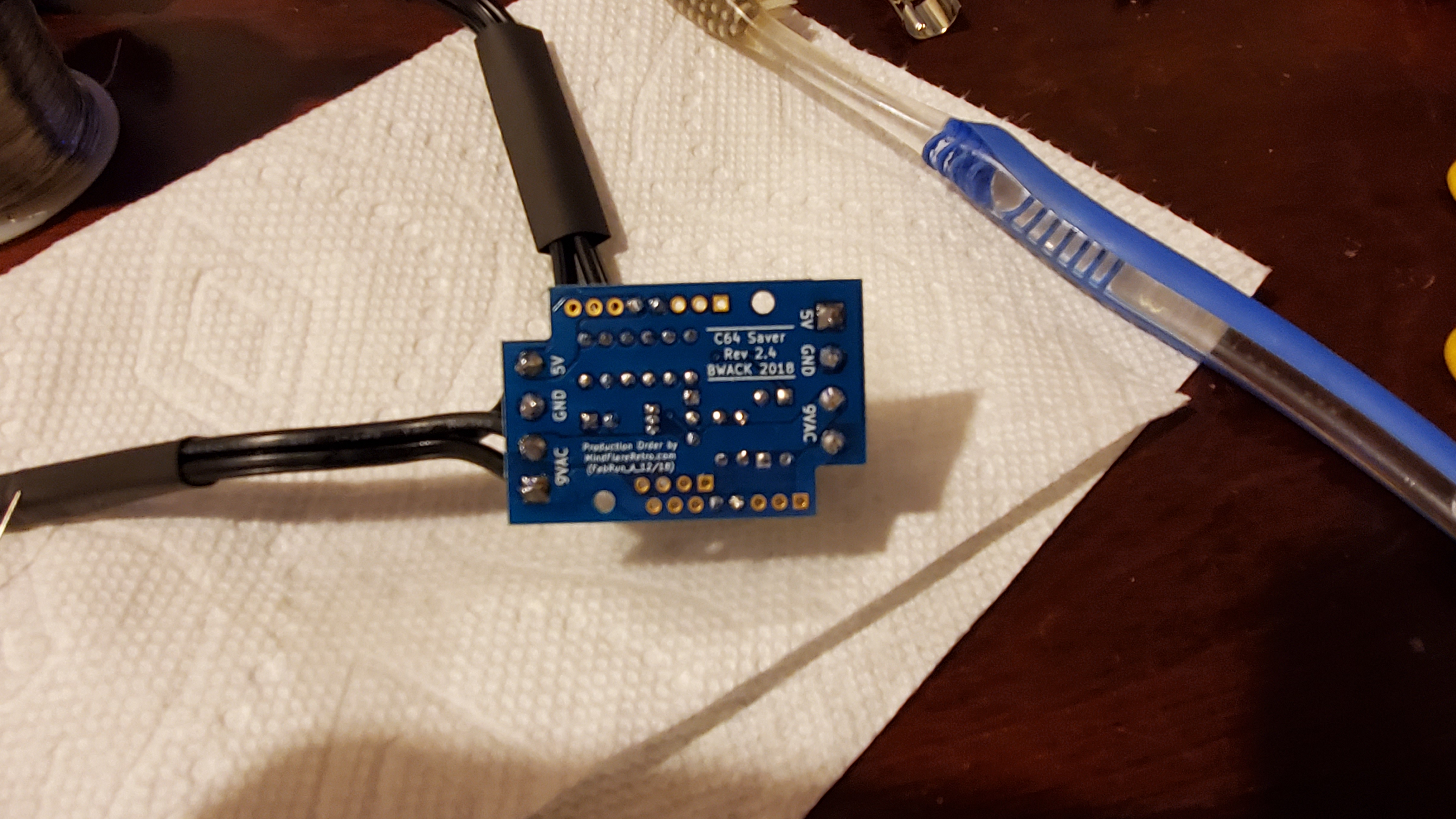
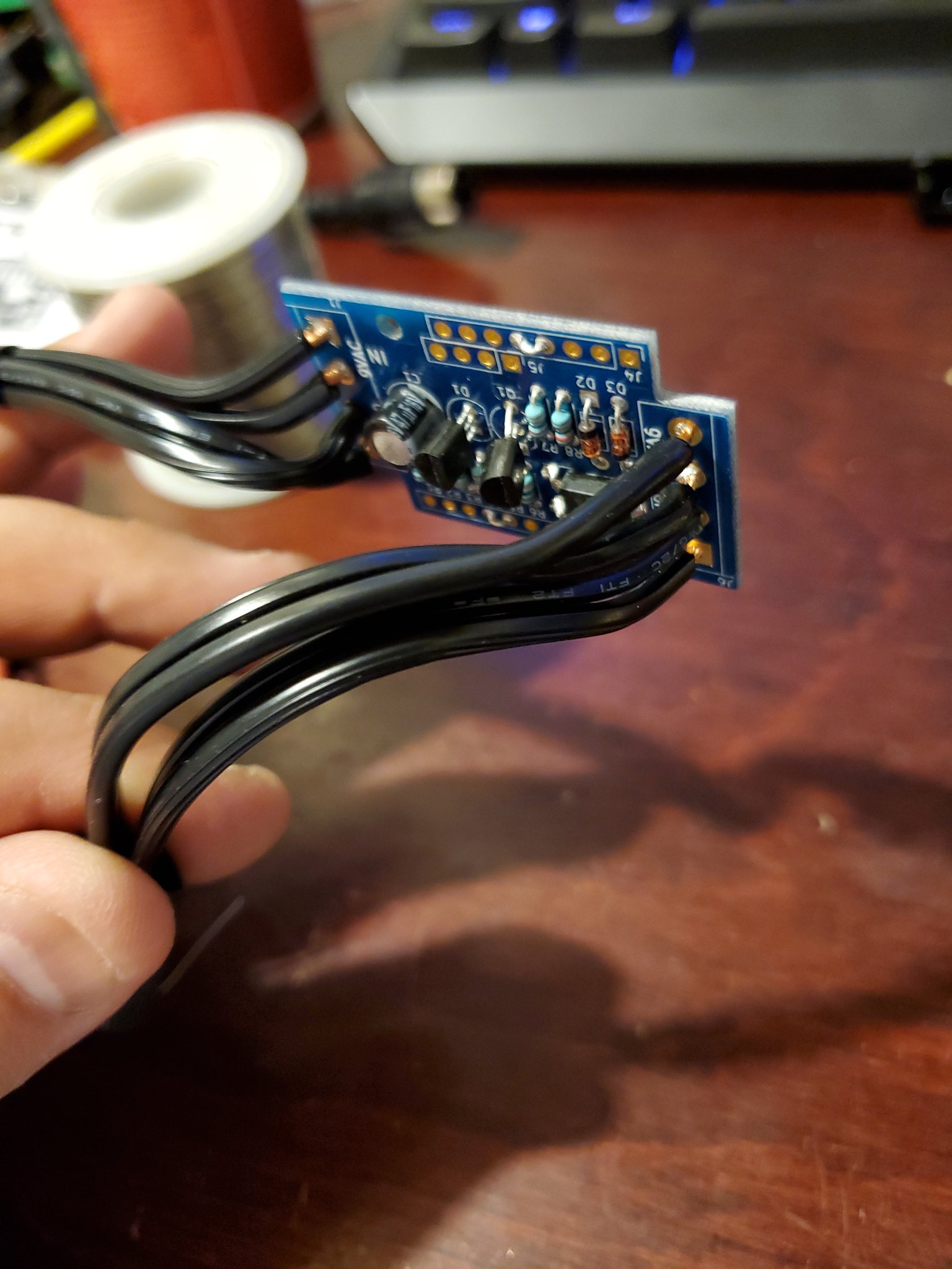
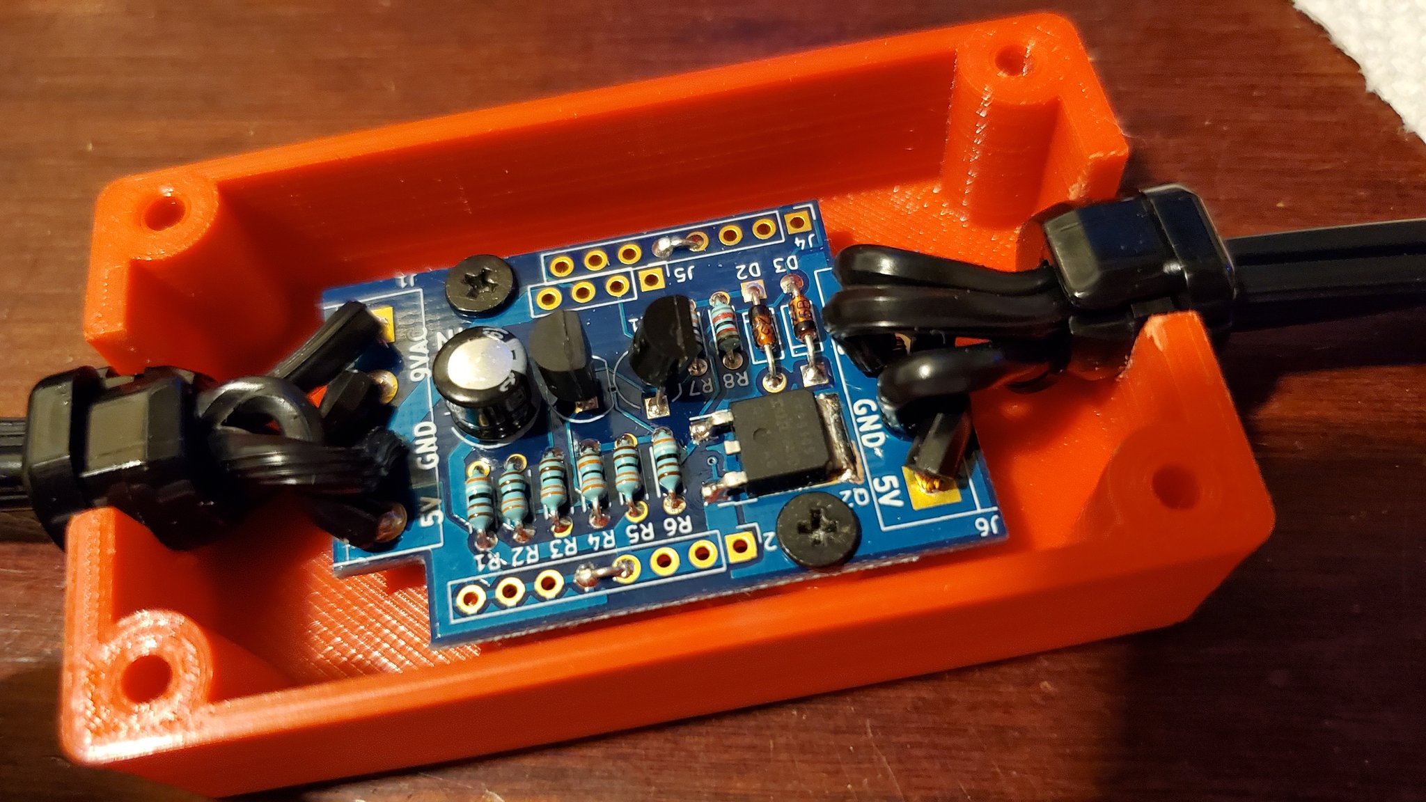
When you're done everything should all fit nicely in the project box.
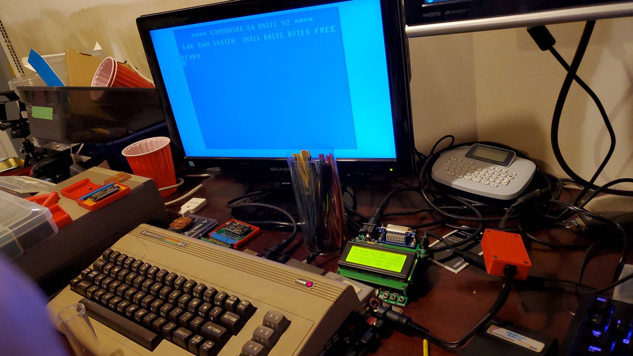
Give it a try and with any luck, your C64 will power right up and be protected. If the 5 volt line creeps up, power should be cut. I happened to have a known bad power supply on hand and was able to test it with that. Alternatively, you can just test it yourself with a bench power supply. Ignore the 9vac lines and just test 5v going in and put a multimeter on the out. You should be able to observe the voltage cut once voltage goes somewhere above 5v. I forget exactly where the cut off is, but it's probably not far.
Project Files
- C64Saver v2.4 - Gerber files for v2.4 through-hole version
- MindFlareRetro C64 v2.4 Parts List w/Links
Releated Links
- GitHub/Bwack - Original Project on GitHub
- MindFlareRetro.com - C64 Saver V2.4 DIY Kits available for sale
- MindFlareRetro Box.Com - C64 Saver V2.4 Parts List w/Links
- MindFlareRetro YouTube - Building a C64 Saver from Scratch
Auditory Pairing
