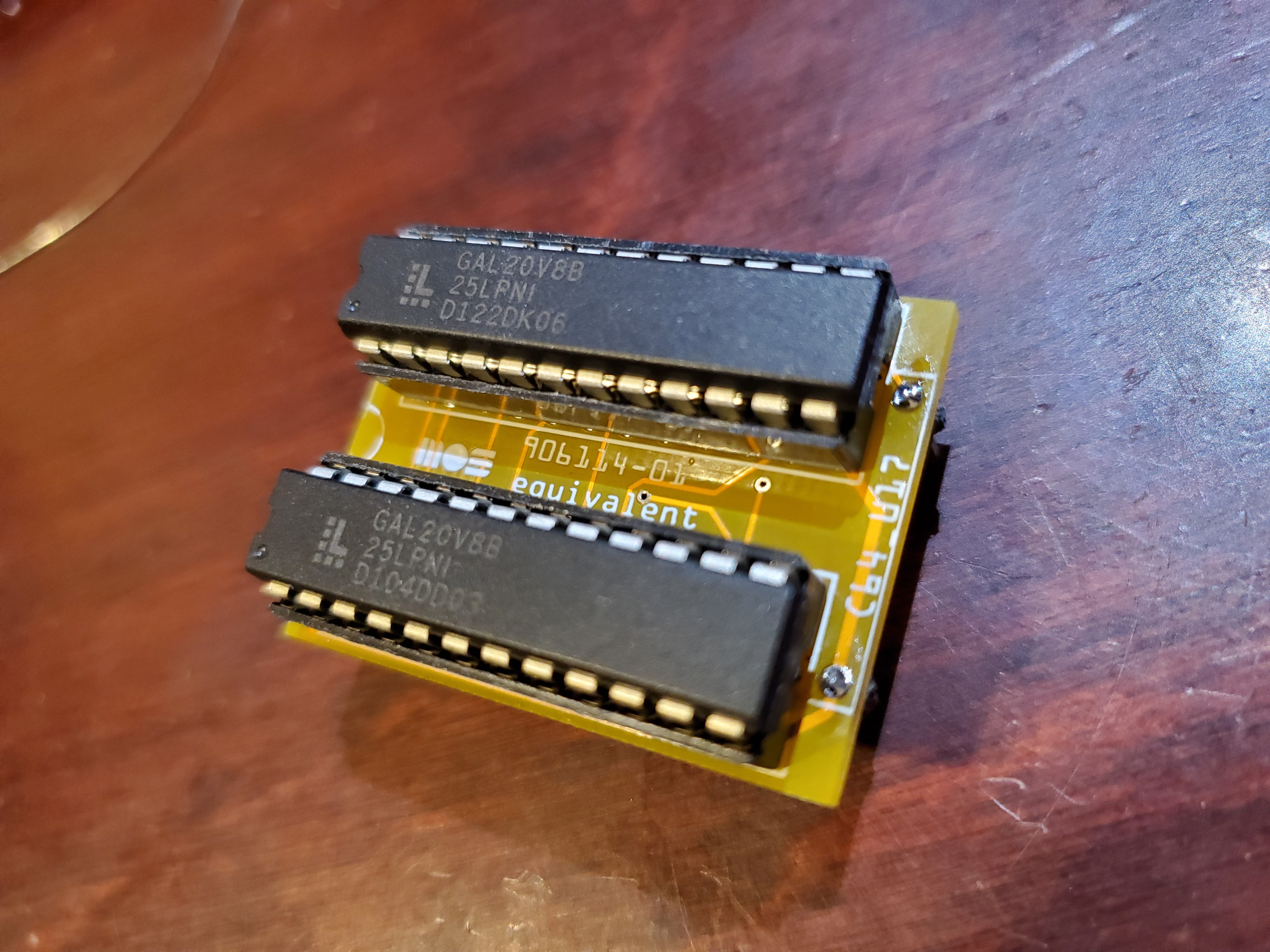
The PLA20V8 is a a very economical, easy to build and highly compatible PLA chip replacement option for the Commodore 64.
Over four decades have passed since the release of the Commodore 64, and as such, many examples are beginning to show their age. Commodore owned their own chip fabrication plant, MOS Technologies, and was therefore able to deliver a very compelling combination of features at a considerably low price.
Unfortunately, MOS had some quality issues with several of their chips, and as a result, Commodore computers tend to suffer from very similar failures in their custom components.
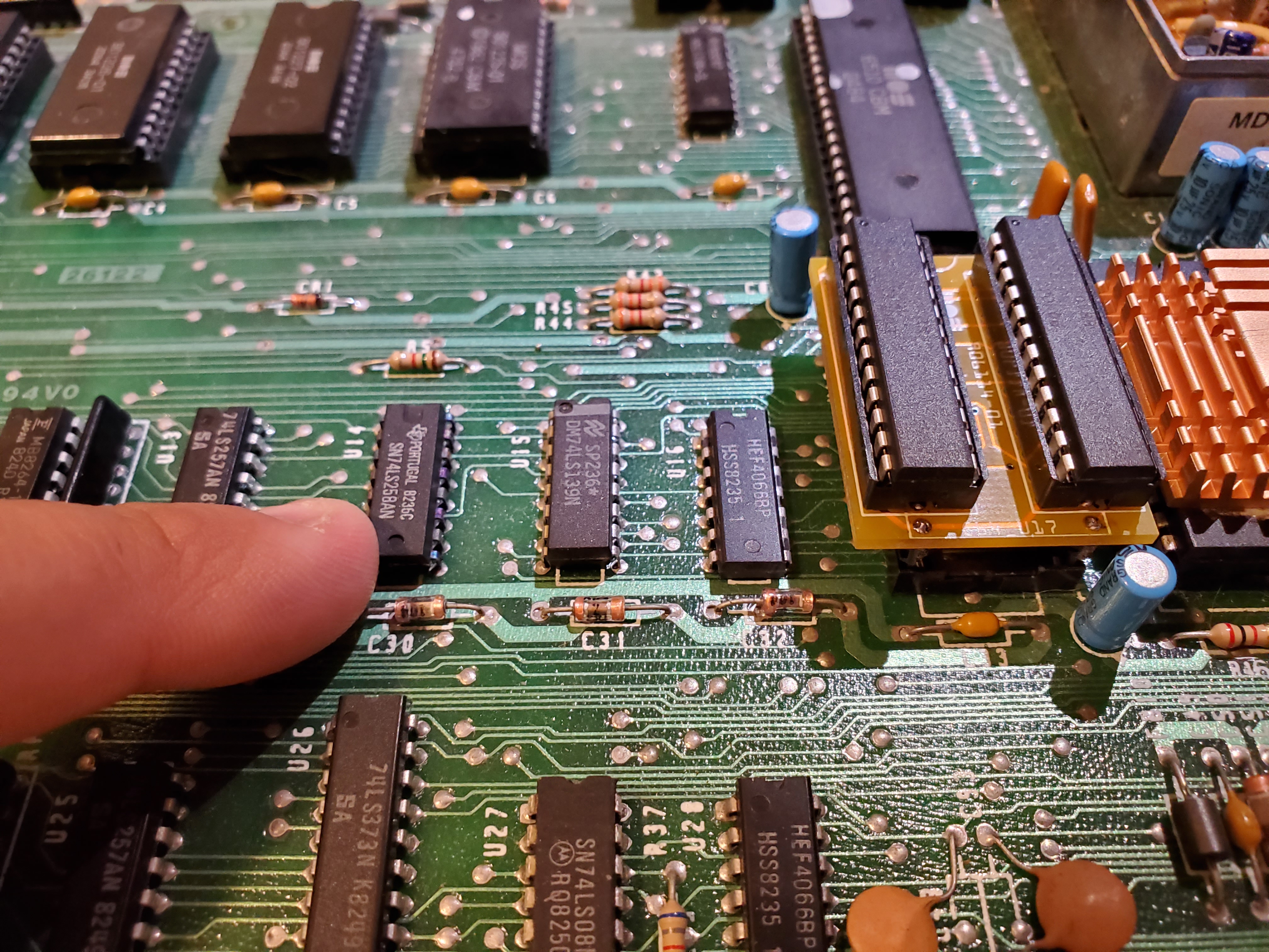
One such chip that is notoriously failure-prone is their Programmable Logic Array, or PLA. This chip is responsible for managing chip selection, memory mapping, and coordination of access to the various components on the system board. The original models used a Signetics 82S100 chip, which is fairly reliable and often found in older C64 units, such as the early 5-pin video models or silver label versions.
Commodore’s 906114-01 "copy" of this programmable chip fails so frequently that it's often the first suspect when diagnosing a faulty computer. In my experience, while it’s indeed a common point of failure, many of the other MOS chips are also prone to issues—most notably the MOS-made versions of the 74 series logic chips and all of the mask ROMs. Other brands of 8-bit computers do not suffer from such widespread chip failures nearly as often as Commodore systems do.
If your C64 is having problems, it may be worth consulting the pictorial fault guide for some guidance before assuming the PLA is at fault. Hopefully your failed part is socketed.
Building the PLA20V8
You will need the printed circuit board and an assortment of parts. You can get a handful of boards produced and mailed to you fairly economically these days from one of the PCB manufacturing companies in China. These are considered prototype boards, and are ofetn offered for as low as $5 for 5 boards 100mm x 100mm or under.
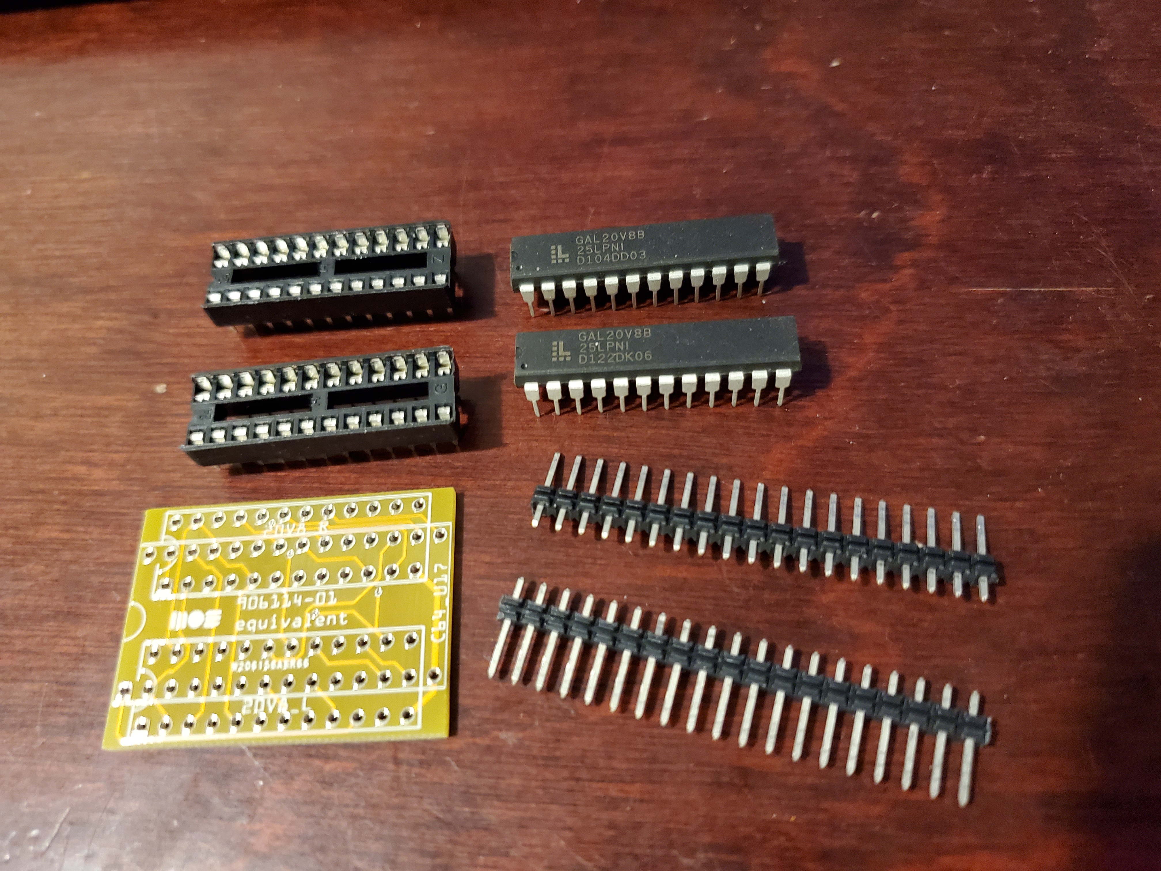
Here you can see the parts I am using. The 2 programmable logic or GAL chips, a couple IC sockets and some header pins. The header pins I'm using are not ideal.. as they will stretch the sockets of whatever IC socket you force them into. I'm comfortable replacing the sockets later so I'm going to go ahead and uses these instead of waiting a month for the nice thin ones from AliExpress to arrive.
Parts List
| Part Ref | Description | Note |
|---|---|---|
| PCB | PLA20V8 Printed Circuit Board | |
| U1,U2 | Lattice GAL 20V8B-25 | 25ns version ideal, but 15ns can be used |
| S1,S2 | 20 Pin IC Socket | Machine pin style may fit easier |
| misc | header pins, ideally thin ones |
Assembly
You will want to solder the pins first, and then you can solder the sockets. Normally I like the standard IC sockets but you might want to use machine pin ones for this board as the solder side of your pins might interfere with the palcement of the sockets.
Programming
There are two GAL's to be programmed here. I used Xegu TL866-II programmer. If you're using the -15ns part, there is a specific version of the JED file to program one of the gals.
| Filename | Note |
|---|---|
| 906114-01-01_20V8_R.jed | This is for the Right GAL, either 25 or 15ns |
| 906114-01_01_20V8_L.jed | This is for a 25ns Left GAL |
| 906114-01_01_20V8_L_alt1.jed | Alternate JED for Left GAL 15ns |
| 906114-01_01_20V8_L_alt2.jed | Alternate JED for Left GAL, 15ns or 25ns |
I used 25ns parts to avoid having to figure out what was the difference was between the two alternate left programming options. There is a description on the original instructions, which I will link to and provide below.
Related Links
Project Files
- 20v8_82s100_adapter_v2_schema.pdf - schematic
- pla20v8-gerbers.zip - PCB Production Gerber files
- 906114-01_20V8_R.jed - Right side GAL content 25ns or 15ns
- 906114-01_20V8_L.jod - Left side GAL content for 25ns only
- 906114-01_20V8_L_alt1.jed - Left side GAL content... refer to original site for details.
- 906114-01_20V8_L_alt2-use-for-15ns.jed - ... refer to original site for details.
Auditory Pairing
